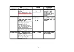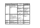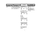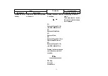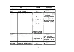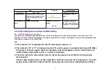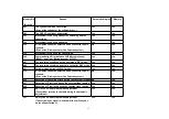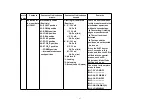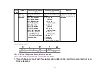
Item
FL display
Key operation
Mode name
Description
(Remote controller key)
Front connection
inspection
Press all front keys and check
the connection between Main
P.C.B. and Front key Switches.
(1) Each time a key is
pressed, segment turned
on increases one by one.
(2) Total umber of keys
that have been pressed.
Press [5] [4] in service
mode.
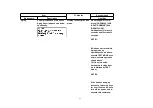
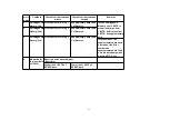
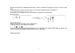
Production Date
Display
Display the date when the unit
was produced.
YY: Year
MM: Month
DD: Day
Press [6] [1] in service
mode.
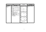
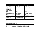
Display the
accumlated
working time
Display the accumulated unit's
working time.
(Indicating unit: Second)
Press [6] [4] in service
mode.
57
Summary of Contents for DMR-ES45VP
Page 7: ...3 Service Navigation 3 1 Service Information 4 Specifications 7 ...
Page 68: ...10 13 Main P C B 1 Disconnect 5 Connectors 2 Remove 2 Screws A and remove Main P C B 52 ...
Page 70: ...11 1 2 Checking and Repairing of Main P C B 54 ...
Page 71: ...11 1 3 Checking and Repairing of RAM Digital P C B Module 55 ...
Page 73: ...11 2 3 Items that should be done after replacing parts 57 ...
Page 74: ...58 ...
Page 75: ......
Page 87: ...17 1 2 Casing Parts Mechanism Section 2 70 ...
Page 88: ...17 1 3 VHS Mechanism Section 71 ...
Page 89: ...17 1 4 Packing Accessories Section 72 ...
Page 111: ...C11701 F2A1A2220055 10V 2200U 1 94 ...
Page 123: ......
Page 124: ......
Page 132: ...1 4 2 4 3 4 4 4 DMR ES45VP ES46VP Main P C B VEPV0054BT 4 4 Section Location Map REAR FRONT ...


