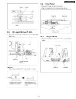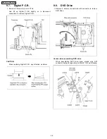
1. Turn off the power and pull out AC cord.
2. Remove the Top Case.
3. Put deck so that bottom can be seen.
4. Slide SLIDE CAM by Eject Pin (JZJ0484) or minus screw driver (small) in the direction of arrow to eject tray slightly.
5. Put deck upward, and push out Tray by Eject Pin (JZS0484) or minus screw driver (small).
13
DMR-EZ27P / DMR-EZ27PC
Summary of Contents for DMR-EZ27P
Page 5: ...2 2 Precaution of Laser Diode 5 DMR EZ27P DMR EZ27PC ...
Page 7: ...3 Service Navigation 3 1 Service Information 3 2 Caution for DivX 7 DMR EZ27P DMR EZ27PC ...
Page 8: ...4 Specifications 8 DMR EZ27P DMR EZ27PC ...
Page 9: ...9 DMR EZ27P DMR EZ27PC ...
Page 10: ...5 Location of Controls and Components 10 DMR EZ27P DMR EZ27PC ...
Page 11: ...11 DMR EZ27P DMR EZ27PC ...
Page 31: ...10 1 2 Checking and Repairing of Main P C B 31 DMR EZ27P DMR EZ27PC ...
Page 34: ...34 DMR EZ27P DMR EZ27PC ...
Page 40: ...DMR EZ27P DMR EZ27PC 40 ...
Page 54: ...DMR EZ27P DMR EZ27PC 54 ...
Page 62: ...DMR EZ27P DMR EZ27PC 62 ...
Page 69: ...15 1 2 Packing Accessories Section 69 DMR EZ27P DMR EZ27PC ...


