7.2.4.2.
(VHS) Condition for clearing the self-diagnosis history
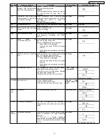
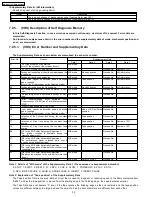
1. A case of that press the STOP key and the EJECT key simultaneously over 5 seconds.
7.2.4.3.
(VHS) Indication of the self-diagnosis history.
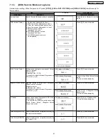
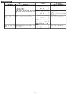
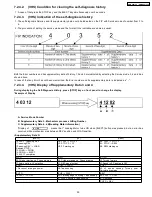
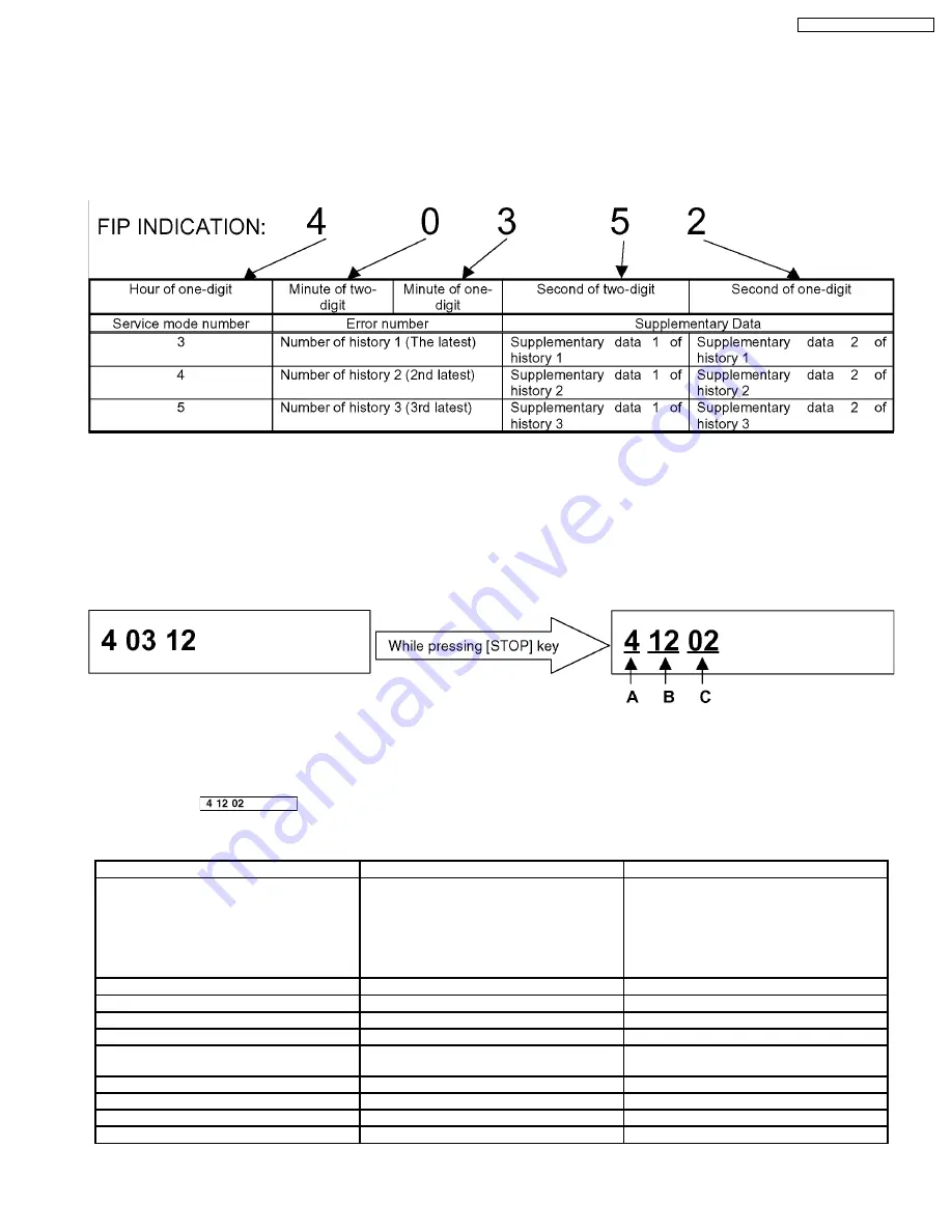
1. The self-diagnosis histories and its supplementary data could be indicated on the FIP with Service mode of number from 3 to
5.
2. The procedure of setting the service mode and the format if the indication are same as usual.
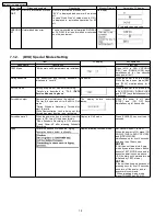
Both the Error numbers and its supplementary data of history 1, 2and 3 are indicated by selecting the Service mode 3, 4 and 5 as
shown above.
In case of that any Error has not been memorized, the Error number and its supplementary data is indicated as " - ".
7.2.4.4.
(VHS) Display of Supplementary Data 3 and 4
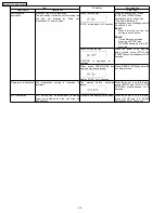
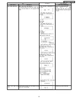
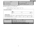
During displaying the Self-Diagnosis History, press [STOP] key on front panel to change the display.
*Example of Display
A: Service Mode Number.
B: Supplementary Data 3...Mechanism process shifting Number.
C: Supplementary Data 4...LM(Loading Motor information)
*Display of
means that " Loading Motor turns ON when [EJECT] button was pressed, but an error has
occurred while mechanism was between REV position and LOAD position.
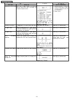
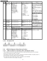
<Supplementary Data 3>
[EJECT]
[FF]
[REW]
10: PLAY
→
passing REV
11: passing REV
12: passing REV
→
LOAD
(Capstan STOP)
13: LOAD
→
DOWN
14: DOWN
→
EJECT
15: EJECT completion
U0: PLAY
→
STOP F
U1: STOP F
→
FF
U2: FF starting up
A0: PLAY
→
STOP F
A1: STOP
→
REW
A2: REW starting up
[PLAY]
[REC]
[STILL]
20: Cylinder starting up, Phase drawing
30: Cylinder starting up, Phase drawing
40:Turning forward
21: Audio muting, VV selection
31: REC signal output
41:Speed is 0, Capstan is OFF
[P.ON]
[STILL
→
PLAY]
[CUE]
-- Process of turning on power
48: Tape sending
49:
x2 speed
sending,
Turning point
of
Calculating remains
[P.OFF]
[CUE
→
PLAY]
[REV]
70: PLAY
→
P.OFF
4A: Finishing edge Checking, Tape sending
80: PLAY
→
P.OFF
4-: PLAY Checking, Tape sending
81: Rewinding
P.OFF
→
REV
29
DMR-EZ47VP / DMR-EZ475VP
Summary of Contents for DMR--EZ475VP
Page 6: ...2 2 Precaution of Laser Diode 6 DMR EZ47VP DMR EZ475VP ...
Page 8: ...3 Service Navigation 3 1 Service Information 3 2 Caution for DivX 8 DMR EZ47VP DMR EZ475VP ...
Page 9: ...4 Specifications 9 DMR EZ47VP DMR EZ475VP ...
Page 10: ...5 Location of Controls and Components 5 1 Each Buttons 10 DMR EZ47VP DMR EZ475VP ...
Page 11: ...11 DMR EZ47VP DMR EZ475VP ...
Page 34: ...9 2 P C B Positions 34 DMR EZ47VP DMR EZ475VP ...
Page 44: ...10 1 2 Checking and Repairing of Main P C B 44 DMR EZ47VP DMR EZ475VP ...
Page 45: ...10 1 3 Checking and Repairing of Digital P C B 45 DMR EZ47VP DMR EZ475VP ...
Page 46: ...10 1 4 Checking and Repairing of DVD 46 DMR EZ47VP DMR EZ475VP ...
Page 48: ...48 DMR EZ47VP DMR EZ475VP ...
Page 49: ...49 DMR EZ47VP DMR EZ475VP ...
Page 52: ...52 DMR EZ47VP DMR EZ475VP ...
Page 60: ...DMR EZ47VP DMR EZ475VP 60 ...
Page 84: ...DMR EZ47VP DMR EZ475VP 84 ...
Page 111: ...15 1 2 Casing Parts Mechanism Section 2 111 DMR EZ47VP DMR EZ475VP ...
Page 112: ...15 1 3 VHS Mechanism Section 112 DMR EZ47VP DMR EZ475VP ...
Page 113: ...15 1 4 Packing Accessories Section 113 DMR EZ47VP DMR EZ475VP ...


