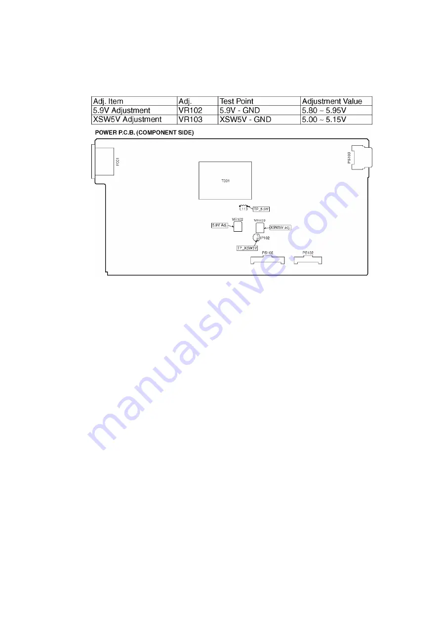
below. If the voltages are out of specification, adjust the voltages
are in the specification as shown below.
8. Assembling and Disassembling
8.1. Disassembly flow chart
The following chart is the procedure for disassembling the casing and inside parts for internal
inspection when carrying out the servicing.
To assemble the unit, reverse the steps shown in the chart below.
17
Summary of Contents for DMRE100HP
Page 13: ...6 2 3 Other Items needed Digital P C B HDD Conditions Nothing special 13 ...
Page 25: ...2 Pull out the HDD holder vertically from Super sheet and HDD 25 ...
Page 56: ...16 3 Packing Accessories Section 56 ...
Page 69: ...69 ...
Page 128: ...Location Map REAR DMR E100H P PC PL Main P C B REP3603B 4 4 Section 1 4 2 4 3 4 4 4 FRONT ...


