355
JAN 2006
Ver. 5.2
DP-3510/3520/3530/4510/4520/4530/6010/6020/6030
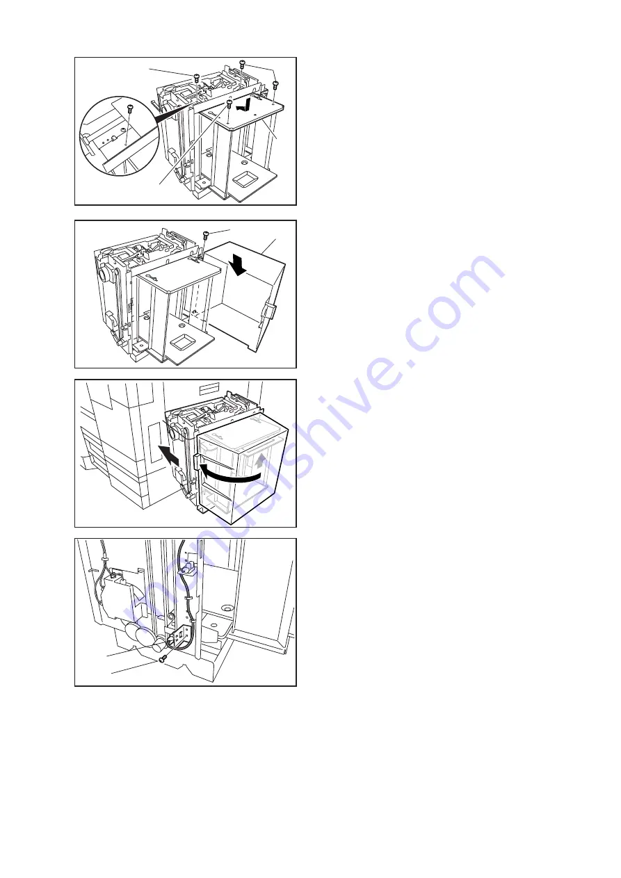
(21) Install the Upper Support Plate by sliding it on
the Guide Screw holes as illustrated.
(22) Secure the Plates with 4 Screws.
(23) Install the
Door (Large)
onto the Mounting Pins.
(24) Secure with 1 Screw.
(25) Place a sheet of paper and close the Door
(Large).
(26) Turn the Power Switches On.
(27) After the Tray comes up, turn the Power
Switches Off.
(28) Remove 1 Screw.
(29) Remove the Sensor Assy from the Letter
Position.
(22)
(22)
(21)
(22)
(24)
(23)
(28)
(29)
Summary of Contents for DP-3530
Page 4: ...4 Beispiel DP 6530 4530 6030 Hinweis ...
Page 424: ...424 JAN 2006 Ver 5 2 DP 3510 3520 3530 4510 4520 4530 6010 6020 6030 ...
Page 425: ...425 JAN 2006 Ver 5 2 DP 3510 3520 3530 4510 4520 4530 6010 6020 6030 ...
Page 474: ...474 JAN 2006 Ver 5 2 DP 3510 3520 3530 4510 4520 4530 6010 6020 6030 memo ...
Page 842: ...memo ...
Page 858: ...DZZSM00298 ...


