386
JAN 2006
Ver. 5.2
DP-3510/3520/3530/4510/4520/4530/6010/6020/6030
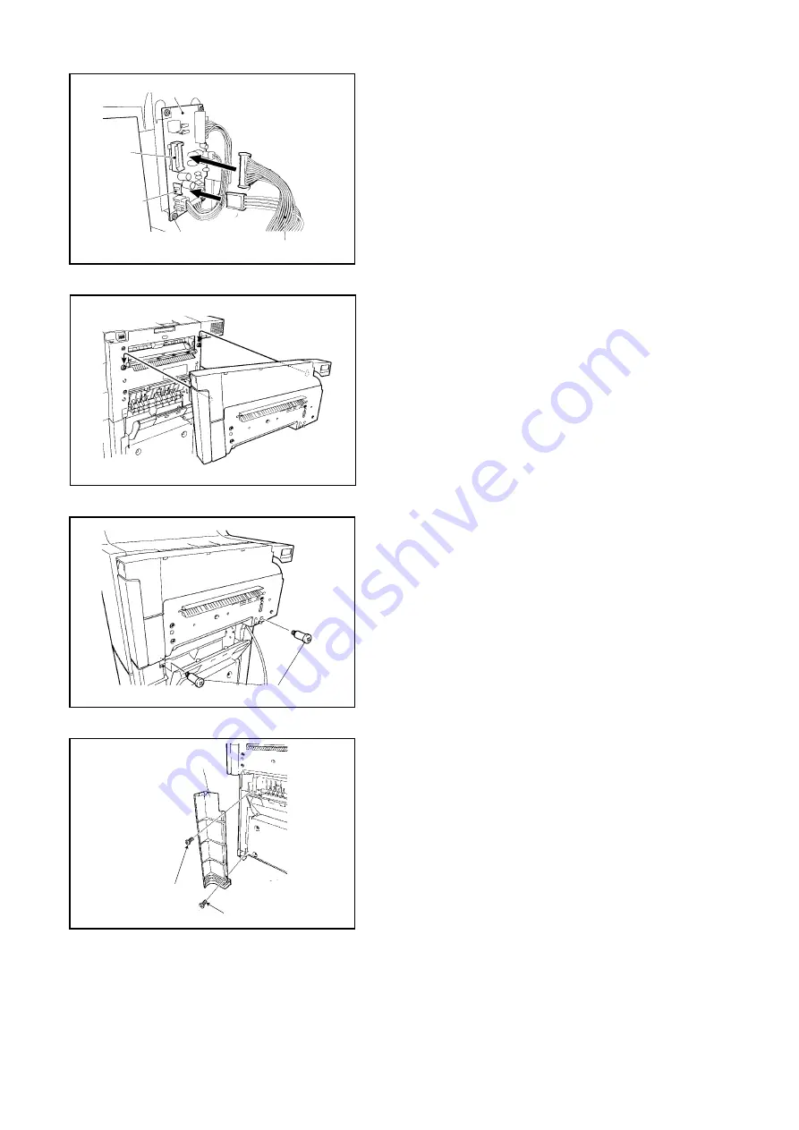
(4) Securely connect one end of the Punch Relay
Harness to J3 and J4 of the Punch Driver PC
Board.
Note:
Loose connections can result in malfunction. If the
Punch Unit malfunctions after installation, try
disconnecting and then re-connecting the
Connector.
(5) Hook the Punch Unit on the Mounting Screw
which was installed in step (2).
(6) Secure the Punch Unit to the Finisher in place
using Shoulder Screws as illustrated.
(7) Secure the Punch Lower Cover to the Finisher
as illustrated with 1 Silver Screw (M4 x 12) at the
top and 1 Black Screw (M4 x 6) at the bottom.
Punch Relay Harness
Punch Driver PCB
J3
J4
Shoulder Screws
(7) Silver M4 x 12
Punch Lower
Cover
(7) Black M4 x 6
Summary of Contents for DP-3530
Page 4: ...4 Beispiel DP 6530 4530 6030 Hinweis ...
Page 424: ...424 JAN 2006 Ver 5 2 DP 3510 3520 3530 4510 4520 4530 6010 6020 6030 ...
Page 425: ...425 JAN 2006 Ver 5 2 DP 3510 3520 3530 4510 4520 4530 6010 6020 6030 ...
Page 474: ...474 JAN 2006 Ver 5 2 DP 3510 3520 3530 4510 4520 4530 6010 6020 6030 memo ...
Page 842: ...memo ...
Page 858: ...DZZSM00298 ...


