507
JAN 2006
Ver. 5.2
DP-3510/3520/3530/4510/4520/4530/6010/6020/6030
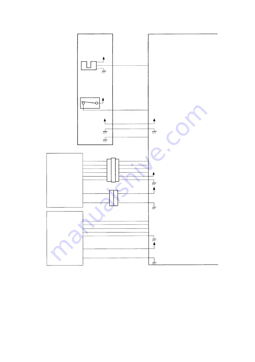
4. Inputs to and Outputs from the Finisher Controller PCB
Fig. 2-006
Stapler Unit
Staple Home
Position Sensor
Staple Switch
PI22
+5V
MS8
+5V
+5V
J8-8
J8-10
J8-11
J8-12
J8-7
STPDRHP*
HOOKEMP*
STPCON*
+5V
Saddle Stitch
Controller PCB
Copier
J131-8
-7
-6
-5
-4
-3
J400-1
-2
-3
-4
-5
-6
J132-1
-2
J500-1
-2
J3-6
-5
-4
-3
-2
-1
J19-1
-2
+24V
+24V
J2-2
-3
-4
-5
-7
J1-1
-2
+24V
Finisher Controller PCB
When a stapler is at the
home position, “0”.
When staple are
present in the cartridge,
“1”.
When the stapler is
connected, “0”.
Communication line
Communication line
Summary of Contents for DP-3530
Page 4: ...4 Beispiel DP 6530 4530 6030 Hinweis ...
Page 424: ...424 JAN 2006 Ver 5 2 DP 3510 3520 3530 4510 4520 4530 6010 6020 6030 ...
Page 425: ...425 JAN 2006 Ver 5 2 DP 3510 3520 3530 4510 4520 4530 6010 6020 6030 ...
Page 474: ...474 JAN 2006 Ver 5 2 DP 3510 3520 3530 4510 4520 4530 6010 6020 6030 memo ...
Page 842: ...memo ...
Page 858: ...DZZSM00298 ...


