605
JAN 2006
Ver. 5.2
DP-3510/3520/3530/4510/4520/4530/6010/6020/6030
5. Removing Upper Delivery Guide Assembly.
6. Removing the PCB Cover.
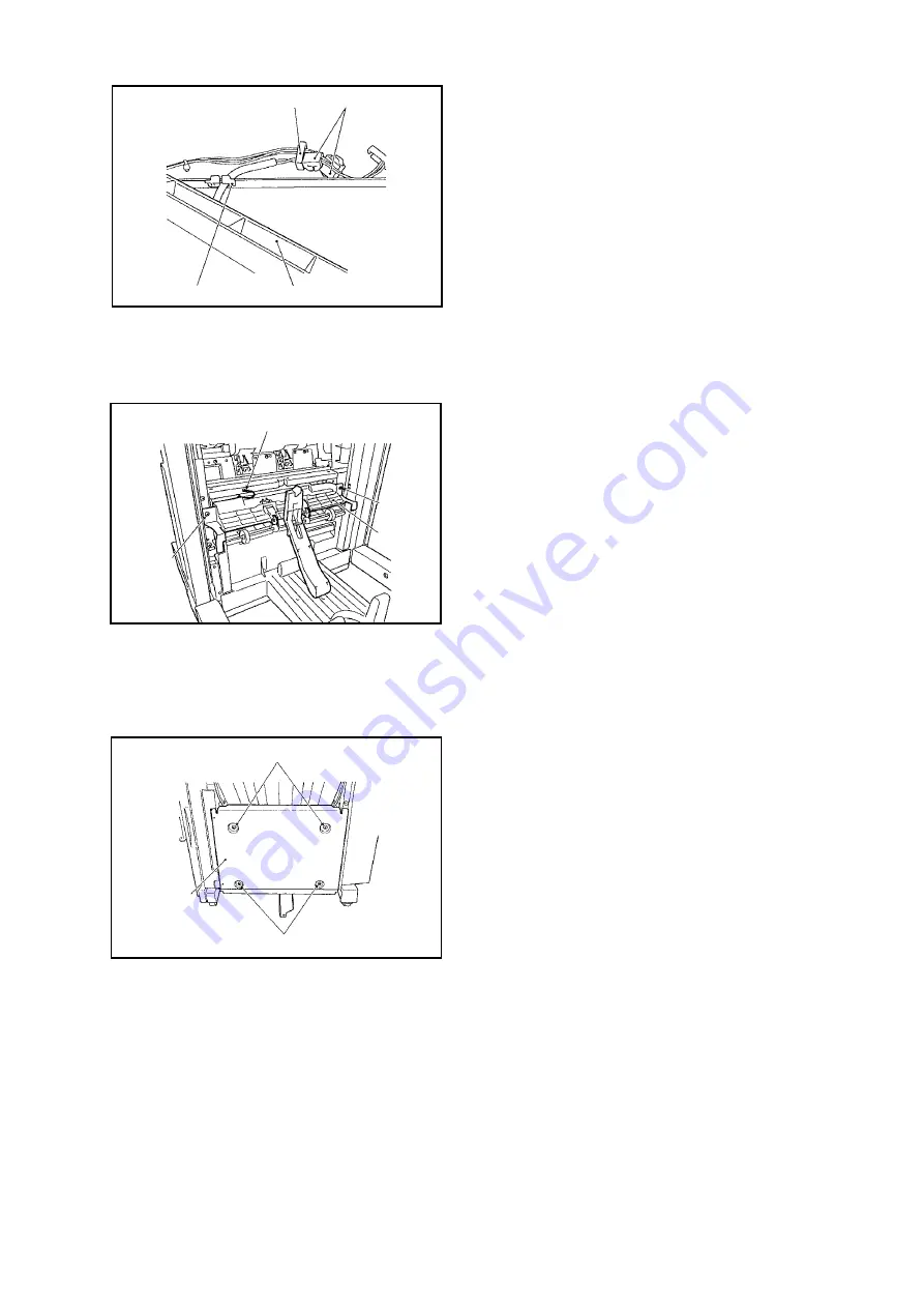
Fig. 5-034
(3) Remove the Harness Leads from the Harness
Stop [5] and Edge Saddle [6].
(4) Disconnect 2 Connectors [7], and remove the
Saddle Delivery Tray Assembly [8].
Fig. 5-035
(1) Remove the Grate-Shaped Lower Guide.
(See Fig. 5-010.)
(2) Remove 2 Screws [1] and Ground Lead [2], and
remove the Upper Delivery Guide Assembly [3].
Fig. 5-036
(1) Remove 4 Screws [4], and remove the PCB
Cover [2].
[5]
[7]
[8]
[6]
[1]
[1]
[2]
[3]
[1]
[1]
[2]
Summary of Contents for DP-3530
Page 4: ...4 Beispiel DP 6530 4530 6030 Hinweis ...
Page 424: ...424 JAN 2006 Ver 5 2 DP 3510 3520 3530 4510 4520 4530 6010 6020 6030 ...
Page 425: ...425 JAN 2006 Ver 5 2 DP 3510 3520 3530 4510 4520 4530 6010 6020 6030 ...
Page 474: ...474 JAN 2006 Ver 5 2 DP 3510 3520 3530 4510 4520 4530 6010 6020 6030 memo ...
Page 842: ...memo ...
Page 858: ...DZZSM00298 ...


