730
JAN 2006
Ver. 5.2
DP-3510/3520/3530/4510/4520/4530/6010/6020/6030
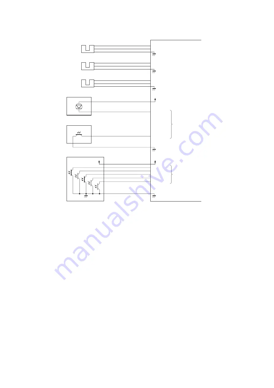
11.3.2.1.4. Inputs to and Outputs from the Punch Controller PCB (Option)
1. Inputs to and Outputs from the Punch Controller PCB
Fig. 2-008
PI1P
J2008-3
-1
-2
+5V
PUNCH
J1006-4
-6
-5
PI2P
J2007-3
-1
-2
+5V
SLIDE
J1006-1
-3
-2
PI3P
J2009-3
-1
-2
+5V
+5V
+5V
+5V
CLOCK
DUSTLED
DUSTPTR
SREG1*
SREG2*
SREG3*
SREG4*
PAEND*
J1006-7
-9
-8
J1005-1
-2
J1005-3
-4
J1007-12
-11
-10
-9
-8
-7
-13
Punch Home
Position Sensor
Horizontal
Registration
Home Position
Sensor
Punch Motor
Clock Sensor
LED121
Waste full LED PCB
PT131
Waste Full Photosensor PCB
Photosensor PCB
PT1
PT2
PT3
PT4
PT5
Punch Controller PCB
When the hole puncher is
at home position, ‘0’.
When the punch slide
unit is at home position,
‘1’.
When the light is
blocked, ‘0’.
When paper is
detected, ‘0’.
While the punch motor
is rotating, alternates
between ‘0’ and ‘1’.
Summary of Contents for DP-3530
Page 4: ...4 Beispiel DP 6530 4530 6030 Hinweis ...
Page 424: ...424 JAN 2006 Ver 5 2 DP 3510 3520 3530 4510 4520 4530 6010 6020 6030 ...
Page 425: ...425 JAN 2006 Ver 5 2 DP 3510 3520 3530 4510 4520 4530 6010 6020 6030 ...
Page 474: ...474 JAN 2006 Ver 5 2 DP 3510 3520 3530 4510 4520 4530 6010 6020 6030 memo ...
Page 842: ...memo ...
Page 858: ...DZZSM00298 ...


