11.4. Optical adjustment
11.4.1. Optical pick gate adjustment
Measurement point
Adjustment point
Mode
Disc
-----
Tangential adjustment screw
(Adjustment screw A)
Radial tilt adjustment screw
(Adjustment screw B)
Tracking servo "ON"
Tracking servo "ON"
DVDT-S01/S15AS
Measuring apparatus
Adjustment value
None (Use the service indication on the main unit)
Adjust the jitter value to the minimum level.
Remove the solder shorts before trying to make the adjustment.
11.4.1.1. Preparations
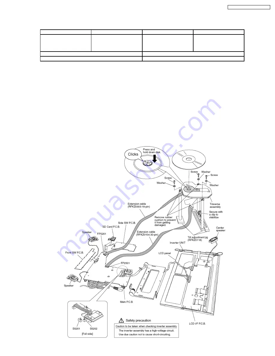
1. Connect the main P.C.B. to the traverse ass’y with the extension cable.
2. Install the traverse ass’y to the tilt adjustment jig with three screws and three washers.
Caution
Remove the rubber cushion of the traverse ass’y.
3. Install the traverse ass’y to the disc.
Caution
Make sure the disc is installed on the disc motor securely.
4. Disassemble the Main P.C.B., Operation P.C.B., Inverter P.C.B. and LCD panel as shown in figure below.
5. The disc cannot be played back with the Disc cover attached. Press and hold down the S5201 and S5202 (Secure with cellulose
tape)
33
DVD-LX110EE / DVD-LX110GCS
Summary of Contents for DVD-LX110EE
Page 12: ...8 DISASSEMBLY REASSEMBLY AND SERVICE POSITION 12 DVD LX110EE DVD LX110GCS ...
Page 13: ...8 1 Disassembly 13 DVD LX110EE DVD LX110GCS ...
Page 14: ...8 2 P C B location 14 DVD LX110EE DVD LX110GCS ...
Page 29: ...29 DVD LX110EE DVD LX110GCS ...
Page 52: ...DVD LX110EE DVD LX110GCS 52 ...
Page 68: ...DVD LX110EE DVD LX110GCS 68 ...
Page 74: ...18 2 Mechanism Section Exploded View 74 DVD LX110EE DVD LX110GCS ...
Page 75: ...18 3 Packing Accessories Exploded View 75 DVD LX110EE DVD LX110GCS ...


