


DISASSEMBLY / REASSEMBLY INSTRUCTIONS
MCUK000601C8
Section 4
Issue 1
Service Manual
– 21 –
Revision 0
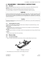
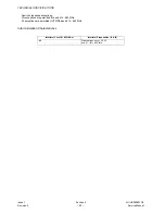
Figure 4.5: GD52 PCB Assembly Removal
4.2.2
Case Removal (GD92 / GD92C)
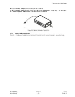
1.
Remove the battery from the back of the telephone. Remove the four case screws located inside the battery compartment.
Figure 4.6: GD92 / GD92C Screw Removal
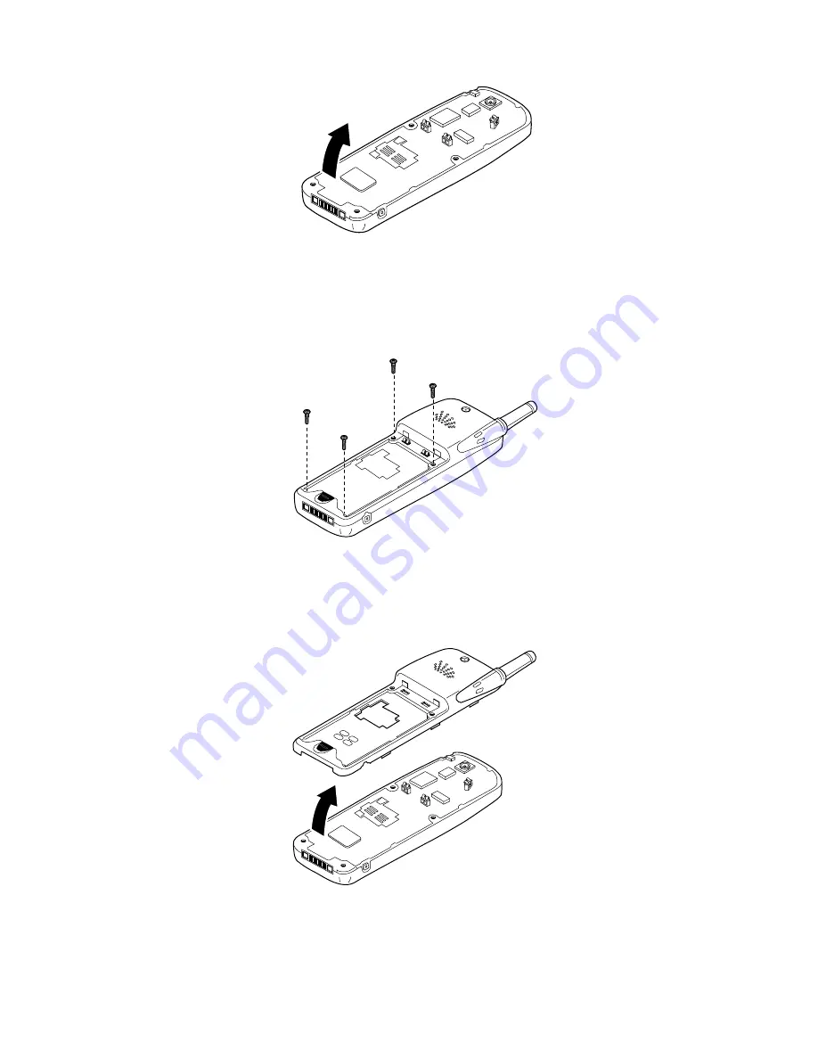
2.
Remove the cover from the case by pulling from the connector end of the telephone. Care must be taken when separating
the case from the cover as the retaining clips may be very stiff. If necessary, re-attach the battery to provide extra support
for the case.
Figure 4.7: GD92 / GD92C Case-Cover Separation
3.
Remove the PCB assembly from the cover.
10194-1
10192-1
10193-1
Summary of Contents for EB-GD52
Page 4: ...Issue 1 iv MCUK000601C8 Revision 0 Service Manual This page is left intentionally blank ...
Page 83: ... 5 8 7 5 06 0 8 6HFWLRQ VVXH 6HUYLFH 0DQXDO 5HYLVLRQ H SDG 3 ...
Page 84: ... 5 8 7 5 06 VVXH 6HFWLRQ 0 8 5HYLVLRQ 6HUYLFH 0DQXDO 7KLV SDJH LV LQWHQWLRQDOO EODQN ...
Page 87: ... 5 8 7 5 06 0 8 6HFWLRQ VVXH 6HUYLFH 0DQXDO 5HYLVLRQ H SDG 3 ...
Page 88: ... 5 8 7 5 06 VVXH 6HFWLRQ 0 8 5HYLVLRQ 6HUYLFH 0DQXDO 7KLV SDJH LV LQWHQWLRQDOO EODQN ...