


TEST AND MEASUREMENT
MCUK000601C8
Section 6
Issue 1
Service Manual
– 47 –
Revision 0
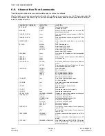
17. Repeat steps 6 to 16 for both low / bottom and high / top channels.
18. Repeat steps 6 to 16 for GSM 1800 on the following channels with the SET AGC 1 field set to 51 dB:
6.6.4.
I and Q Values
NOTE:
With the I, Qch adjustment procedures, the transmitter must be set to Power Level 5 (this represents the worst
case of non-linearity) so care must be taken that the spectrum analyser used can accept a signal input of
33 dBm. If not, an appropriate attenuator must be used.
I, Q ch Offsets
Spectrum analyser setup:
Centre frequency
= 902.4 MHz
RBW = 10 kHz
VBW = 10 kHz
span = 1 MHz
sweep time
= 2 sec
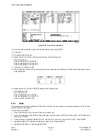
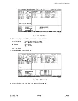
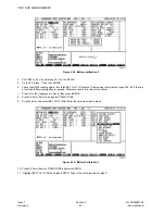
1.
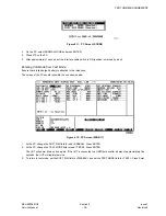
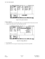
Set the Channel box to channel 62 at power level 5, nominal burst modulated with all 1’s, as shown below:
Figure 6.23: Channel box setup
2.
On the spectrum analyser, measure the image leak ratio.
Image leak ratio is the measured ratio of peak power and the power at 135 kHz below peak frequency.
Example:
Peak power = 33dB
Power at 135 kHz below peak power = -9 dBm
Image leakage ratio = 33 dBm - (-9dBm) = 42 dBm
Channel
GSM 900
Low / bottom
1
Mid
60
High / top
111
Channel
GSM 1800
Bottom / low
512
Mid
650
High / top
885
Summary of Contents for EB-GD52
Page 4: ...Issue 1 iv MCUK000601C8 Revision 0 Service Manual This page is left intentionally blank ...
Page 83: ... 5 8 7 5 06 0 8 6HFWLRQ VVXH 6HUYLFH 0DQXDO 5HYLVLRQ H SDG 3 ...
Page 84: ... 5 8 7 5 06 VVXH 6HFWLRQ 0 8 5HYLVLRQ 6HUYLFH 0DQXDO 7KLV SDJH LV LQWHQWLRQDOO EODQN ...
Page 87: ... 5 8 7 5 06 0 8 6HFWLRQ VVXH 6HUYLFH 0DQXDO 5HYLVLRQ H SDG 3 ...
Page 88: ... 5 8 7 5 06 VVXH 6HFWLRQ 0 8 5HYLVLRQ 6HUYLFH 0DQXDO 7KLV SDJH LV LQWHQWLRQDOO EODQN ...


