DISASSEMBLY / REASSEMBLY INSTRUCTIONS
Issue 1
Section 4
MCUK010801C8
Revision 0
– 20 –
Service Manual
2.
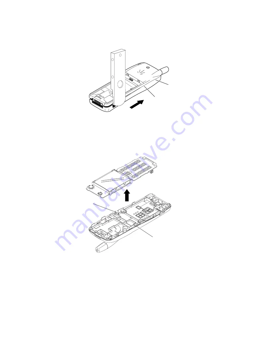
Carefully prise apart the case and cover, creating a gap at the base I/O connector. Insert the Case Separation Tool (see
Section 6) into the gap created, and gently slide the tool in the direction shown, ensuring that the moulded hooks separate
all the way up to point ‘A’.
Figure 4.2: Case-Cover Separation
3.
Repeat step 2 for the opposite side of the telephone. Carefully twist the cover so that the hooks at position ‘B’ and those
at the corresponding position on the opposite side of the phone separate.
4.
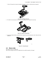
Using a small screwdriver blade or similar blunt object, depress one of the RF Shield lugs (marked ‘A’ and ‘B’ in the diagram
below) to release the PCB from the case.
Figure 4.3: PCB Assembly Removal
10467-1
A
B
10464-1
A
B
Summary of Contents for EB-GD95
Page 64: ...LAYOUT DIAGRAMS MCUK010801C8 Section 9 Issue 1 Service Manual 60 Revision 0 D C E A B F 3 4 ...
Page 66: ...CIRCUIT DIAGRAMS on 9 Issue 1 Revision 0 GD95 Circuit Diagram Logic A4 A4 ...
Page 67: ...CIRCUIT DIAGRAMS Issue 1 Section 9 Revision 0 58 Figure 9 2 GD95 Cir A4 A4 ...
Page 68: ...9 MCUK010801C8 Service Manual GD95 Circuit Diagram RF A4 A4 EB GD95 EBGD95C ...


