TEST AND MEASUREMENT
MCUK010801C8
Section 6
Issue 1
Service Manual
– 35 –
Revision 0
3.
On the PC, select NORMAL MODE and press ENTER.
4.
Press Shift F10 on the PC.
5.
After approximately 1 second, set the ExtPwr switch to ON until the unit powers up.
Enter Call Mode from Test Mode
Ensure that a fully-charged battery is attached to the telephone.
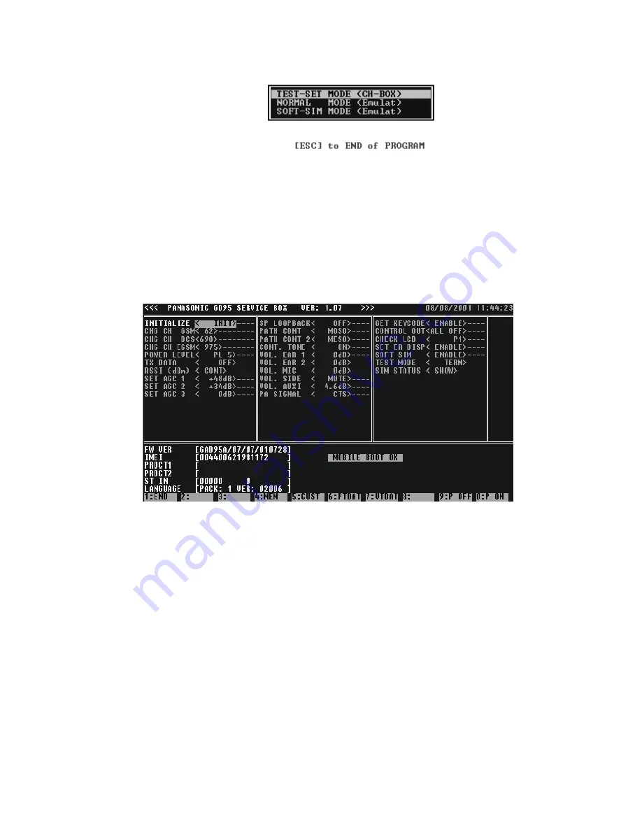
The screen of the PC should resemble the one shown below:
Figure 6.11: PC Screen (SCRN11)
1.
At the PC, change the SOFT SIM field to read <ENABLE>. Press ENTER.
2.
At the PC, change the TEST MODE field to read <TERM>. Press ENTER.
The UUT will power down and up again. If the UUT is connected to a GSM test set, after a delay of approximately five
seconds, the UUT will register service.
3.
To return to test mode, set the SOFT SIM field to <DISABLE> and set the TEST MODE field to <TEST>. Press Enter.
Channel Box software loaded and the screen indication as follows
Figure 6.10: PC Screen (SCRN9)
Summary of Contents for EB-GD95
Page 64: ...LAYOUT DIAGRAMS MCUK010801C8 Section 9 Issue 1 Service Manual 60 Revision 0 D C E A B F 3 4 ...
Page 66: ...CIRCUIT DIAGRAMS on 9 Issue 1 Revision 0 GD95 Circuit Diagram Logic A4 A4 ...
Page 67: ...CIRCUIT DIAGRAMS Issue 1 Section 9 Revision 0 58 Figure 9 2 GD95 Cir A4 A4 ...
Page 68: ...9 MCUK010801C8 Service Manual GD95 Circuit Diagram RF A4 A4 EB GD95 EBGD95C ...

