EBL512 G3 V. 3.0.X
- FIRE ALARM SOLUTIONS OPERATING INSTRUCTIONS
56
21. FAULT MESSAGES
Below follows a list of all fault messages, in alphabetical order. There is also an explanation to each fault.
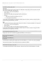
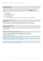
Checksum fault in downloaded data.
Control unit will now restart
A fault in the downloaded Site Specific Data (SSD). After the restart a new fault will be generated:
FAULT: Site Specific Data (SSD), control unit xx.
A new SSD download will probably solve the problem.
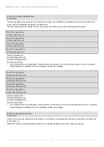
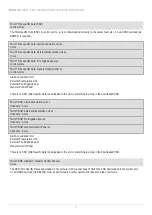
FAULT: 24V for AAU xx, (Primary channel), CU xx
FAULT: 24V for FBP xx, (Primary channel), CU xx
FAULT: 24V for EPU xx, (Primary channel), CU xx
FAULT: 24V for GCP xx, (Primary channel), CU xx
The AAU/FBP/EPU/GCP unit xx, connected to control unit no. xx, has no power on its 24V primary input.
Check cables / connections / fuses etc.
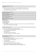
FAULT: 24V for AAU xx, (Secondary channel), CU xx
FAULT: 24V for FBP xx, (Secondary channel), CU xx
FAULT: 24V for EPU xx, (Secondary channel), CU xx
FAULT: 24V for GCP xx, (Secondary channel), CU xx
The AAU/FBP/EPU/GCP unit xx, connected to control unit no. xx, has no power on its 24V secondary input.
Check cables / connections / fuses etc.
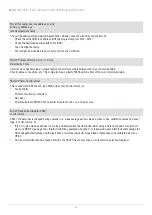
FAULT: 24V for Display Unit (Fxx), CU xx
xx = Fuse number(18 or 19), xx = 00-29.
Check fuse F18 or F19 on the main board in control unit no. xx.
Fuse: T1.6AH 250V.
These 24V outputs, together with the 24V output for routing equipment, are also protected by an auto-reset
-
table fuse PTC2 (max 3.15A). If this fault message occurs and the fuse is not blown, check the 24V outputs
for combined overload.
FAULT: 24V for expansion board (auto-resettable), CU xx
xx = 00-29.
The auto-resettable fuses PTC4 and PTC12 (total max 1A) has been activated. Check for overload on the expansion board’s
outputs.
To reset the PTC, remove the load and wait 5 min to let the PTC cool down before re-connecting the load.

