9
4.3.
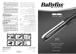
Lead wire of Iron Plate (Heater A , Heater B) and Circuit arrangement
points.
1. Lead wire of Iron Plate (Heater A assembly block) and (Micro) PCB Assembly 200C arrangement follow as below.
2. Lead wire of Iron Plate (Heater B assembly block) and (High Voltage Igniter) PCB Assembly arrangement follow as below.
3. Lead wire of Moisture Assembly Block arrangement follow as below.
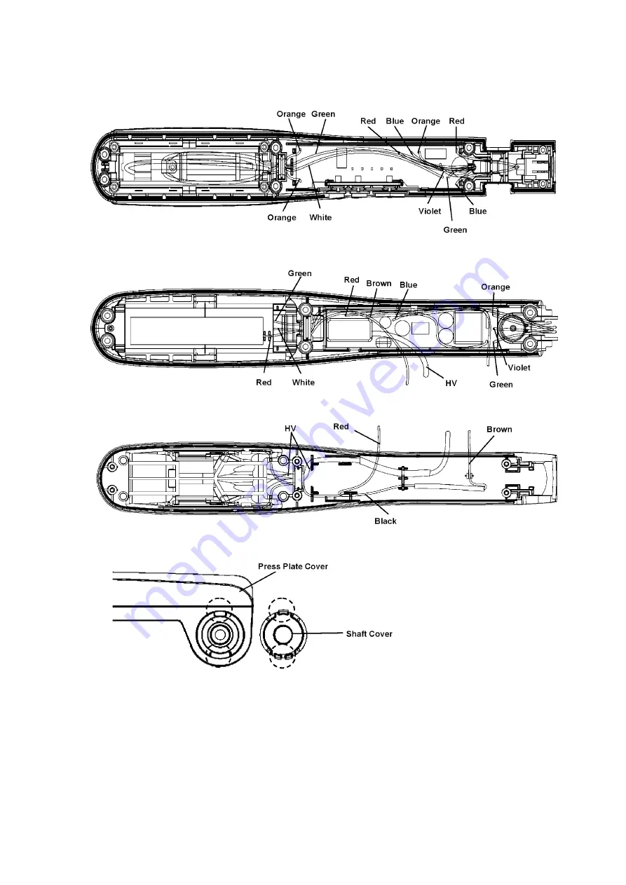
4. Shaft Cover must be control direction follow as below.
Summary of Contents for EH-HS95
Page 3: ...3 3 Troubleshooting Guide Refer to Wiring Connection Diagram ...
Page 4: ...4 ...
Page 10: ...10 5 Wiring Connection Diagram ...
Page 11: ...11 6 Schematic Diagram ...