background image

6

4.2.

Assembly Instructions

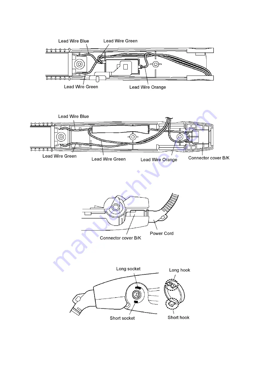
1. Arrange Lead wire into rib of Press plate as shown in Figure 13.

(Figure 13)

• Arrange Lead wire into rib of Housing A as shown in Figure 14.

(Figure 14)

2. Assembly Housing B together with Housing A as shown in Figure 15.

• Ensure that the power cord is attached to the connector cover. (Apply grease floil at the power cord terminal)

(Figure 15)

3. Fixing Shaft cover follow hook direction as shown in Figure 16.

(Figure 16)

Summary of Contents for EH-HW19

Page 1: ... EH HW19 Asia TABLE OF CONTENTS PAGE PAGE 1 Warning 2 2 Specifications 2 3 Troubleshooting Guide 3 4 Disassembly and Assembly Instructions 4 4 1 Disassembly Instructions 4 4 2 Assembly Instructions 6 5 Wiring Connection Diagram 7 6 Schematic Diagram 8 7 Exploded View and Replacement Parts List 9 7 1 Exploded View 9 7 2 Replacement Parts List 10 ...

Page 2: ...ng point is 50 70 F 30 40 C higher Please use a soldering iron with temperature control and adjust it to 750 20 F 400 10 C In case of using high temperature solder ing iron please be careful not to heat too long Pb free solder will tend to splash when heated too high about 1100 F 600 C 2 Specifications ...

Page 3: ...3 3 Troubleshooting Guide Refer to SCHEMATIC DIAGRAM ...

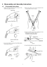
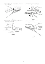
Page 4: ... the Shaft screw and take off the Shaft from Main body as shown in Figure 5 Figure 5 3 Remove the spring by pull out the Housing side and Press plate side as shown in Figure 6 Figure 6 4 Using a screwdriver remove the two tapping screw from Press plare cover as shown in Figure 7 Be careful not to lose the spring Figure 7 5 Take off the Press plate cover as shown in Figure 8 Figure 8 ...

Page 5: ...shown in Figure 9 Figure 9 7 Using screwdriver remove the 2 tapping screw and 1 torx screw as shown in Figure 10 Figure 10 8 Take off the Housing B as shown in Figure 11 Figure 11 9 Remove the Iron Plate ass y B K of Housing side as shown in Figure 12 Figure 12 ...

Page 6: ...wire into rib of Housing A as shown in Figure 14 Figure 14 2 Assembly Housing B together with Housing A as shown in Figure 15 Ensure that the power cord is attached to the connector cover Apply grease floil at the power cord terminal Figure 15 3 Fixing Shaft cover follow hook direction as shown in Figure 16 Figure 16 ...

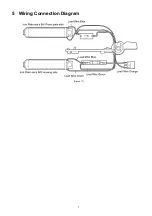
Page 7: ...7 5 Wiring Connection Diagram Figure 17 ...

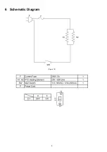
Page 8: ...8 6 Schematic Diagram Figure 18 ...

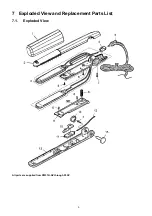
Page 9: ...9 7 Exploded View and Replacement Parts List 7 1 Exploded View All parts are supplied from PMFTH AP through PLAP ...

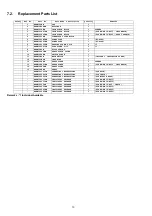
Page 10: ... EHHW19PPCBW PRESS PLATE COVER 1 10 EHHW19SPBW SWITCH PLATE 1 11 EHHW19MSW MAIN SWITCH 1 INCLUDE 2 INSULATION TUBES 12 EHHW19LWDW LEAD WIRE 1 13 EHHW19PPBW PRESS PLATE 1 OTHERS 13 EHHW19PP41BW PRESS PLATE 1 FOR EH HW19 K415 INDONESIA 14 EHHW19SHCBW SHAFT COVER 1 15 EHHW19SHBW SHAFT 1 EHHW1941S03W OPERATING INSTRUCTIONS 1 FOR ASIA EHHW1962S03W OPERATING INSTRUCTIONS 1 FOR INDIA EHHW1969S03W OPERATI...

Reviews: