background image

5

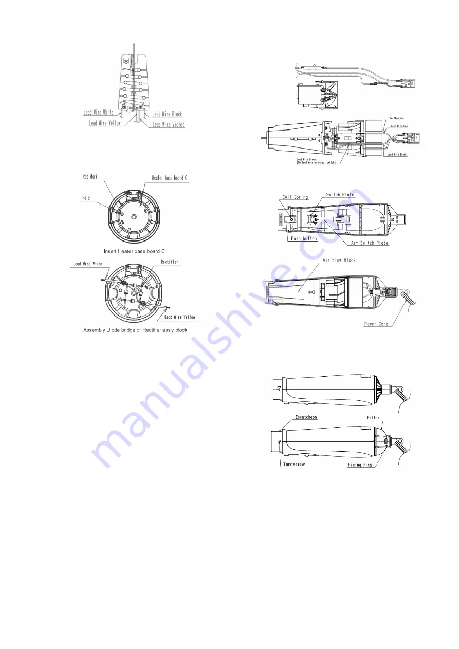
4. Insert Heater base board C to Motor ass'y block and

assembly Diode bridge of Rectifier ass'y block to Motor 's
terminalsby solder.

5. Assembly Select switch to Motor ass'y block ,insert two

Lead wires (Black and Red) into slot of Air flow regulator.

6. Assembly Parts into Housing B step by step.

7. Assembly Housing A&B together, assembly Fixing ring,

Filter, Escutcheon to Housing A&B and in the end tighter
two Torx screws.

Summary of Contents for EH-KA12

Page 1: ... Guide 3 4 Disassembly and Assembly Instructions 4 4 1 Disassembly Instructions 4 4 2 Assembly Instructions 4 5 Wiring Connection Diagram 6 6 Schematic Diagram 7 7 Exploded View and Replacement Parts List 8 7 1 Model No EH KA12 Exploded View for EH KA12 8 7 2 Model No EH KA12 Parts List 9 7 3 Model No EH KA23 Exploded View for EH KA23 10 7 4 Model No EH KA23 Parts List 11 7 5 Model No EH KA42 Expl...

Page 2: ...ring iron please be careful not to heat too long Pb free solder will tend to splash when heated too high about 1100 F 600 C 2 Specifications Sell Area or Country China 495 Number of Model EH KA12 EH KA23 EH KA42 Power source AC 220V 50Hz Power consumption 550W Air volume with attachment 0 43 m3 min Air flow temperature in case of room temperature 30 C 120 C Cord length A2 Plug 1 7 m Weight Roller ...

Page 3: ...3 3 Troubleshooting Guide ...

Page 4: ...ousing A and B by unfastening Housing B at indicated area 4 2 Assembly Instructions 1 Assembly Select switch to Heater blocka and Connector cover by soldering Lead wires connect to the positions 2 Assembly Connector cover block to Heater block by sol dering Lead wires connect to the positions 3 Assembly Rectifier ass y block to Heater block by solder ing Lead wires connect to the positions ...

Page 5: ...otor s terminalsby solder 5 Assembly Select switch to Motor ass y block insert two Lead wires Black and Red into slot of Air flow regulator 6 Assembly Parts into Housing B step by step 7 Assembly Housing A B together assembly Fixing ring Filter Escutcheon to Housing A B and in the end tighter two Torx screws ...

Page 6: ...6 5 Wiring Connection Diagram ...

Page 7: ...7 6 Schematic Diagram ...

Page 8: ...8 7 Exploded View and Replacement Parts List 7 1 Model No EH KA12 Exploded View for EH KA12 ...

Page 9: ...1 B2 PLUG 6 EHKA12MB9W MOTOR BLOCK 1 7 EHKA12SSW SELECT SWITCH 1 INCLUDE 3 INSULATION TUBES 8 EHKA12ITBW INSULATION TUBE 3 3PCS PACK 9 EHKA12ASPWW ARM SWITCH PLATE 1 10 EHKA12HB9W HEATER ASSEMBLY BLOCK 1 11 EHKA12RFB9W RECTIFIER ASSEMBLY BLOCK 1 12 EHKA12CSHW COIL SPRING 1 13 EHKA12PBWW PUSH BUTTON 1 14 EHKA12SPWW SWITCH PLATE 1 15 EHKA12T2604W TORX SCREW 2 1 16 EHKA12ESW ESCUTCHEON 1 17 EHKA12BAW...

Page 10: ...10 7 3 Model No EH KA23 Exploded View for EH KA23 ...

Page 11: ...3MB9W MOTOR BLOCK 1 7 EHKA23SSW SELECT SWITCH 1 INCLUDE 3 INSULATION TUBES 8 EHKA23ITBW INSULATION TUBE 3 3PCS PACK 9 EHKA23ASPPW ARM SWITCH PLATE 1 10 EHKA23HB9W HEATER ASSEMBLY BLOCK 1 11 EHKA23RFB9W RECTIFIER ASSEMBLY BLOCK 1 12 EHKA23CSHW COIL SPRING 1 13 EHKA23PBPW PUSH BUTTON 1 14 EHKA23SPPW SWITCH PLATE 1 15 EHKA23T2604W TORX SCREW 2 1 16 EHKA23ESW ESCUTCHEON 1 17 EHKA23BAPW BLOW BRUSH 1 18...

Page 12: ...12 7 5 Model No EH KA42 Exploded View for EH KA42 ...

Page 13: ... SELECT SWITCH 1 INCLUDE 3 INSULATION TUBES 8 EHKA42ITBW INSULATION TUBE 3 3PCS PACK 9 EHKA42ASPWW ARM SWITCH PLATE 1 10 EHKA42HB9W HEATER ASSEMBLY BLOCK 1 11 EHKA42RFB9W RECTIFIER ASSEMBLY BLOCK 1 12 EHKA42CSHW COIL SPRING 1 13 EHKA42PBWW PUSH BUTTON 1 14 EHKA42SPWW SWITCH PLATE 1 15 EHKA42T2604W TORX SCREW 2 1 16 EHKA42ESW ESCUTCHEON 1 17 EHKA42BAWW BLOW BRUSH 1 18 EHKA42BRAWW ROLLER BRUSH 1 19 ...

Reviews: