background image

Tips of assembling

1. Attach the Ottoman pipe cloth.

2. Attach the parts to the Ottoman pipe B and tie the cord with two 

Insulated ties.

33

PDF created with pdfFactory Pro trial version 

www.pdffactory.com

Summary of Contents for EP1061-P1

Page 1: ...ORDER NO HPD0309P04C1 MASSAGE LOUNGER EP1061 P1 SPECIFICATIONS SPECIFICATIONS 1 PDF created with pdfFactory Pro trial version www pdffactory com ...

Page 2: ...ectric Industrial Co Ltd All rights reserved Unauthorized copying and distribution is a violation of law 1 COMPONENTS IDENTIFICATION 1 1 Massage lounger 2 PDF created with pdfFactory Pro trial version www pdffactory com ...

Page 3: ...1 2 Controller 3 PDF created with pdfFactory Pro trial version www pdffactory com ...

Page 4: ...LLING REGIONAL ROLLING Width adjustment Approx 60 to 150mm Intensity adjustment Shiatsu Swedish Knead vibration Tap A Tap B whole back roll and Regional roll from gentle to strong 55mm wide adjustability where massage heads push out toward body as intensity increases 4 PDF created with pdfFactory Pro trial version www pdffactory com ...

Page 5: ...power socket 2 Turn the lock switch to the open position 3 Turn on the power switch on the back of the unit When the operating lock switch is pointing toward lock the power switch cannot be moved to the on position 5 PDF created with pdfFactory Pro trial version www pdffactory com ...

Page 6: ...ition As a further caution unplug the power cord from the power socket after each use Always keep the key in a safe place Timer When the on off button is pushed a timer begins to prevent overuse After approximately 15 minutes time expires and the massage wheel goes into storage position 4 REQUIRED TOOLS 6 PDF created with pdfFactory Pro trial version www pdffactory com ...

Page 7: ...5 ACTUAL WIRING DIAGRAM 5 1 Massage mechanism 7 PDF created with pdfFactory Pro trial version www pdffactory com ...

Page 8: ...IME Total use time While pushing the and the intensity adjustment buttons simultaneously turn on the power switch and continue to hold the buttons for approximately 5 seconds Release after the on off 8 PDF created with pdfFactory Pro trial version www pdffactory com ...

Page 9: ... buttons after reading the total use time Chart for reading each function use time Button operation Function for reading use time LED display for confirming function Shiatsu Shiatsu Shiatsu LED lights up Swedish Swedish Swedish LED lights up Kneading Kneading Kneading LED lights up Vibration Vibration Vibration LED lights up Tapping A Tapping A Tapping A LED lights up Tapping B Tapping B Tapping B...

Page 10: ...AGER UP DOWN SENSOR GEAR ADJUSTMENT METHOD When the massager is removed from the chair the position of the up down sensor gear changes resulting in a change of the up down stop position When installing the massager on the back frame be sure to adjust the position with the up down 10 PDF created with pdfFactory Pro trial version www pdffactory com ...

Page 11: ...izontally by moving the massager to the position shown in the Figure Unless the massager has been mounted horizontally an abnormal sound or problem may occur 5 Move it up to the highest position until the massager stops by setting the controller manual operation MASSAGE HEAD ADJUSTMENT button to up 6 Peeping into the square hole of the back frame check the position of the massager to adjust One th...

Page 12: ...the massage heads adjustment switch to level 1 and check the up down stroke 9 DISASSEMBLY AND ASSEMBLY INSTRUCTION COSMETIC PART AND CHAIR CONSTRUCTION 9 1 Removing the Head rest Back rest cushion Arm rest 1 Unzip the zippers and remove the Back cushion with pillow 2 Remove nine brush clips on each sides which fix the Arm rest left and the right with a slotted screwdriver This procedure is unneces...

Page 13: ...sary so as to remove the Seat 4 Remove eight Push return rivets which fix the Under cover left and the right with a crossed screwdriver and remove the Under cover left and the right 5 Push the core of the Push rivets 4pcs with screwdrivers etc and 13 PDF created with pdfFactory Pro trial version www pdffactory com ...

Page 14: ...the Seat and cut the Insulated tie and remove the Seat 9 2 Removing the Massage mechanism block 1 Lift the Ottoman a little bit and push up the Interlock link and remove it 14 PDF created with pdfFactory Pro trial version www pdffactory com ...

Page 15: ...Interlock link and remove it 3 Remove three Rail piece installation screws and remove the Rail piece 4 Remove four Cover for P C B installation screws and remove the Cover for P C B 15 PDF created with pdfFactory Pro trial version www pdffactory com ...

Page 16: ...power supply one screw and two connectors 6 Remove two plastic rivets on the Massage mechanism cover and take off the Message mechanism cover and remove the Cover clip 16 PDF created with pdfFactory Pro trial version www pdffactory com ...

Page 17: ...o take away the block obstructed by the bottom metal piece of the Rear frame If the distance is less than 9cm adjust the distance moving the Width belt on the right side of the Massage mechanism block using fingers 9 3 Removing the parts of the Massage mechanism block You can work from 1 to 12 without taking away the Massage mechanism block 17 PDF created with pdfFactory Pro trial version www pdff...

Page 18: ...ors on the Main circuit board 2 Remove the ground wire and two screws 3 Remove two Insulated ties 4 Remove two screws and three Circuit board spacers 18 PDF created with pdfFactory Pro trial version www pdffactory com ...

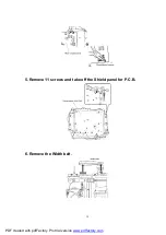
Page 19: ...5 Remove 11 screws and take off the Shield panel for P C B 6 Remove the Width belt 19 PDF created with pdfFactory Pro trial version www pdffactory com ...

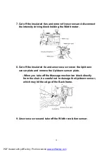
Page 20: ...rew a screw on the Up down sensor plate and remove the Up down sensor plate When you take off the Massage mechanism block directly from the chair be careful not to damage the Up down sensor which may hit the edge of the Back frame 9 Unscrew a screw and take off the Width revolution sensor 20 PDF created with pdfFactory Pro trial version www pdffactory com ...

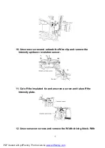
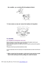
Page 21: ...e the Intensity up down revolution sensor 11 Cut off the Insulated tie and unscrew a screw and take off the Intensity plate 12 Unscrew seven screws and remove the Width driving block With 21 PDF created with pdfFactory Pro trial version www pdffactory com ...

Page 22: ...nge of the up down stop position When installing the massager on the back frame be sure to adjust the position with the up down detection gear Up down detection gear position adjustment procedure To make an adjustment refer to the massager removing method the back frame is tilted from the chair 1 Before mounting the massager on the back frame must be moved down to the lowest position by setting th...

Page 23: ...utton to up 6 Peeping into the square hole of the back frame check the position of the massager to adjust One thread of the up down detection gear gives a stroke change of 4mm When the massager has been raised excessively Turn the up down detection gear counterclockwise to adjust When the massager has been lowered excessively Turn the up down detection gear clockwise to adjust While adjusting the ...

Page 24: ...emoving the Head rest Back rest cushion Arm rest 2 Cut off the Insulated tie on the Seat 3 Unscrew six screws The work will be easy if the Massage mechanism block is take out If you work with the Massage mechanism block on the chair move the Massage mechanism block up and down and unscrew six screws 24 PDF created with pdfFactory Pro trial version www pdffactory com ...

Page 25: ...6 Removing the Under box 1 Follow the procedure 4 of 9 1 Removing the Head rest Back rest cushion Arm rest 2 Unscrew the screw and pull out a Rod holder and slide the Under box up right outward 25 PDF created with pdfFactory Pro trial version www pdffactory com ...

Page 26: ...Insulated tie T30R SF binding the Connecting cord for the power source etc 9 7 Removing the Power source switch block 1 Unscrew two screws and cut off the Insulated tie 26 PDF created with pdfFactory Pro trial version www pdffactory com ...

Page 27: ...nd take off the Connector and take off the Controller block 3 Unscrew two screws and cut off the Insulated tie 4 After removing screws you can remove the Micro switch Power source cord Fuses etc 27 PDF created with pdfFactory Pro trial version www pdffactory com ...

Page 28: ... the Power source switch block plate with two screws so that the cords will be stored through the ditch and bind the Insulated tie to the Main frame which is bundling cords First fix the Power source switch then bundle cords with Insulated tie and install it to the Main frame 28 PDF created with pdfFactory Pro trial version www pdffactory com ...

Page 29: ... 4 of 9 1 Removing the Head rest Back rest cushion Arm rest 3 Follow the procedure 2 to 3 of 9 6 Removing the Under box 4 Take off two connectors CN111 CN103 as the figure 5 Take off the Hinge pin large and the Snap pin large and take off the Lift unit It will be easier to take off the Lift unit if moving down the Massage mechanism block first 29 PDF created with pdfFactory Pro trial version www p...

Page 30: ...ip the zippers of the Roller ottoman cloth and remove it 3 Remove six screws from the Ottoman cloth and remove the Ottoman cloth and remove six screws from the Roller ottoman case B and remove the Roller ottoman case B 30 PDF created with pdfFactory Pro trial version www pdffactory com ...

Page 31: ... Removing the Under box and remove the connector of the Roller ottoman Sub circuit CN300 white 4 Pull out the zipper ends connecting the Seat and the Ottoman and cut the Insulated tie and unzip the zippers Cut the Insulated tie connecting the Ottoman pipe cloth and Ottoman pipe and pull down the Ottoman pipe cloth 31 PDF created with pdfFactory Pro trial version www pdffactory com ...

Page 32: ...pe and pull out the cord Pull out the slit pin 6 Remove the Shaft holder case screws 4pcs Roller ottoman gear box screws 4pcs and remove the Roller and the Roller ottoman motor 32 PDF created with pdfFactory Pro trial version www pdffactory com ...

Page 33: ...Tips of assembling 1 Attach the Ottoman pipe cloth 2 Attach the parts to the Ottoman pipe B and tie the cord with two Insulated ties 33 PDF created with pdfFactory Pro trial version www pdffactory com ...

Page 34: ...3 Screw the Roller ottoman case B and the Roller ottoman cloth each six screws 4 Zip the Roller ottoman cloth 34 PDF created with pdfFactory Pro trial version www pdffactory com ...

Page 35: ...5 Install the Roller ottoman unit to the Ottoman pipe with the Hex nut M8 35 PDF created with pdfFactory Pro trial version www pdffactory com ...

Page 36: ...EXAMINATION AFTER INSPECTION AND PREPAIRING Check all operations with the massage block operation test switch Check that the massage block operates using the controller Check that the massage block operates loaded i e sit in the chair 36 PDF created with pdfFactory Pro trial version www pdffactory com ...

Page 37: ... chair make sure that it has enough space to fully recline There should be more than 40cm between the wall and the chair when in the upright position 11 TROUBLESHOOTING 11 1 Main unit 37 PDF created with pdfFactory Pro trial version www pdffactory com ...

Page 38: ...11 2 Controller Massage mechanism block 38 PDF created with pdfFactory Pro trial version www pdffactory com ...

Page 39: ...11 3 Air bags 39 PDF created with pdfFactory Pro trial version www pdffactory com ...

Page 40: ...40 PDF created with pdfFactory Pro trial version www pdffactory com ...

Page 41: ...41 PDF created with pdfFactory Pro trial version www pdffactory com ...

Page 42: ...12 EXPLODED VIEW 42 PDF created with pdfFactory Pro trial version www pdffactory com ...

Page 43: ...43 PDF created with pdfFactory Pro trial version www pdffactory com ...

Page 44: ...44 PDF created with pdfFactory Pro trial version www pdffactory com ...

Page 45: ...45 PDF created with pdfFactory Pro trial version www pdffactory com ...

Page 46: ...46 PDF created with pdfFactory Pro trial version www pdffactory com ...

Page 47: ...s long as the destinations or the Massage loungers to which each parts should be installed are not specified each parts can be installed to any EP1061 Massage loungers 47 PDF created with pdfFactory Pro trial version www pdffactory com ...
Page 48: ...ELT 1 25 WEP2200L1847 UP DOWN SENSOR PLATE 1 26 WEP1061L1397 UP DOWN SENSOR GEAR 1 27 WEP2200L2187 UP DOWN SENSOR 1 28 WEP596L6057 UP DOWN SHAFT BOLT 2 29 WEP579L3530 FITTING 2 30 WEP2200L1447 PINION B BLOCK 1 31 WEP545H1937 GUIDE ROLLER B 2 32 WEP578AL0317 RUBBER RING 2 33 WEP2200L0337 UP DOWN SHAFT B 2 34 WEP2200L0377 UP DOWN SHAFT 1 35 WEP2200L1797 UP DOWN GEAR BOX 2 36 WEP2200L1427 UP DOWN WOR...

Page 49: ...NGLE M5 16 2 77 WEP1061K3907 CASTOR 2 78 WEP2110K3187 PIPE END 1 79 WEP578K3377 SEAT PLATE 4 80 WEP760N9607 WASHER HEAD TAPPING SCREW K4 10 4 81 WEP1260L1538 OTTOMAN LIFT UNIT 1 82 WEP1061L1547 OTTOMAN ROLLER LINK 1 83 WEP1260L1678 OTTOMAN INTERLOCK LINK 1 84 WEP1061L1597 OTTOMAN LINK A 1 85 WEP1061L1607 OTTOMAN LINK B 1 86 WEP2200L0907 HINGE PIN LARGE 2 87 WEP589L0351 SNAP PIN LARGE 2 88 WEP2000L...

Page 50: ...BLOCK 1 132 WEP2110L0267 UNDER BOX TOP RIGHT 1 133 WEP1260L0277 UNDER BOX TOP LEFT 1 134 WEP2000L0717 ROD HOLDER C 2 135 WEP2110L3758 EDGE GUARD TOP 1 136 WEP2000L6017 SCREW CUP S M3 5 1 137 WEP1061L2108 SUB CIRCUIT BOARD 1 138 WEP2110L0227 HEATPROOF SHEET 1 139 WEP2110L3527 EDGE GUARD 1 140 WEP1260L2638 POWER SOURCE TRANSFORMER 1 141 WEP578L9537 SCREW CUP S K4 8 2 142 WEP2110L3137 PROTECTION BOAR...

Page 51: ...P1060K3638 ARMREST LEFT USA 1 160 WEP1061K3718 ARMREST LEFT CANADA 1 161 WEP1260K3858 UNDER COVER RIGHT 1 162 WEP1260K3868 UNDER COVER LEFT 1 163 WEP596K0457 RIVET 8 WEP1061L8008 PACKAGING FOR EP1061K234 1 WEP1061L8018 PACKAGING FOR EP1061K264 1 WEP1061L8088 MANUALS FOR EP1061K234 1 WEP1061L8098 MANUALS FOR EP1061K264 1 WEP1260L4008 MASSAGE MECHANISM BLOCK 1 51 PDF created with pdfFactory Pro tria...

Reviews: