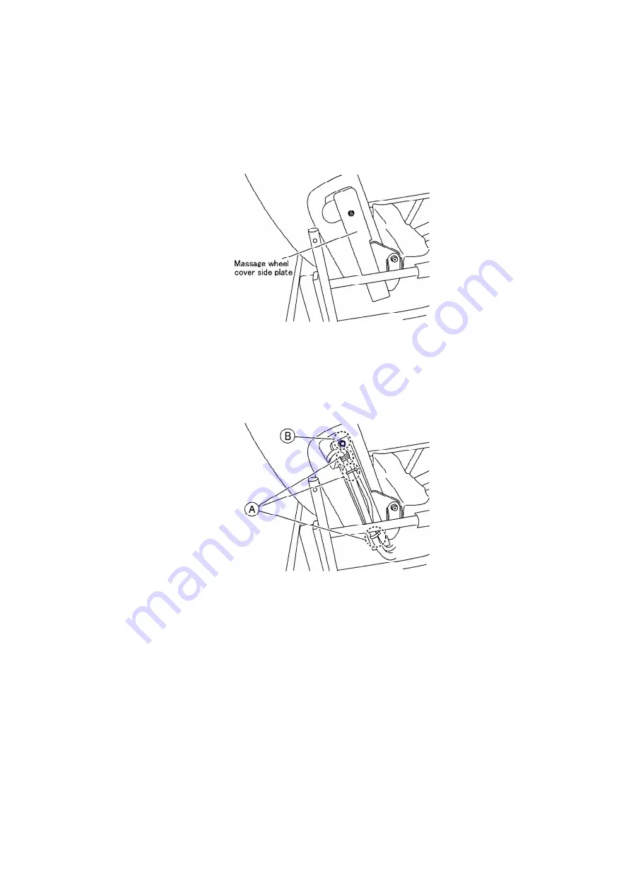
5. Unscrew two screws on each Massage wheel cover side plates
and remove the Massage wheel cover side plates.
6. Cut off three Insulated ties (A) on the right side and unscrew a
bolt on each sides.
Remove the Massage wheel cover.
7.5. Removing the Power source switch box
1. Unscrew two screws on the inner side.
27
Summary of Contents for EP1272-U1
Page 1: ...ORDER NO HPD0508U23C1 MASSAGE LOUNGER EP1273 U1 EP1272 U1 SPECIFICATIONS SPECIFICATIONS 1 ...
Page 3: ...1 1 2 EP1272 3 ...
Page 4: ...1 2 Controller 4 ...
Page 8: ...5 ACTUAL WIRING DIAGRAM 8 ...
Page 22: ...12 Unscrew four screws and remove the Massage gear block 22 ...
Page 26: ...3 Unscrew eight screws 4 Cut off five Insulated ties 26 ...
Page 36: ...36 ...
Page 37: ...37 ...
Page 41: ...11 EXPLODED VIEW 41 ...
Page 42: ...42 ...
Page 43: ...43 ...
Page 44: ...44 ...
Page 45: ...45 ...
Page 46: ...46 ...


