13.2 Removing the massager
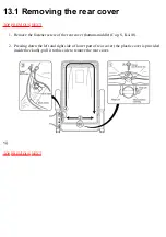
1. Remove the two installation screws from the massager cover, and take off the cover.
2. Push down the seatback to the front part.
•Inspection and repair are done after placing the chair as explained in 1. and 2. above.
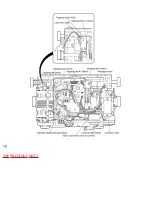
3. Remove the rail piece set screws (K4-6), 3 pieces (left and right) shown in Figure 9 , and
remove the rail pieces A and B.
4. When the massager moves up and down (normally), move it down to the lowest position by
setting the controller manual operation up/down button to "DOWN", and then turn clockwise
the up/down clutch hex nut M6 (see Figure 9) tomove to the position where the Pinion A and B
block is visible from the back frame.
*When the massager fails to move up and down, turn clockwise the hex nut M6 of up/down
clutch.
(The massager can be moved by attaching the hex socketø10 (for nut 6 mm) to a rechargeable
drill driver.)
5. Remove the three connectors (red, yellow, white, blue, brown) of the power connecting cord
connected to the massager, remove one screw (K4-6) fixing the massager side cord clip, and
remove the power connecting cord from the massager.
6. In this state the massager can be taken out.
Summary of Contents for EP790-C1
Page 2: ... TOP NEXT ...
Page 4: ... TOP PREVIOUS NEXT ...
Page 8: ... TOP PREVIOUS NEXT ...
Page 10: ... TOP PREVIOUS NEXT ...
Page 15: ...4 1 PARTS IDENTIFICATION TOP PREVIOUS NEXT TOP PREVIOUS NEXT ...
Page 16: ...4 2 TURNING ON THE POWER TOP PREVIOUS NEXT ...
Page 17: ...TOP PREVIOUS NEXT ...
Page 18: ...5 Required tools TOP PREVIOUS NEXT ...
Page 19: ...TOP PREVIOUS NEXT ...
Page 20: ...6 Simplified wiring diagram TOP PREVIOUS NEXT ...
Page 21: ... TOP PREVIOUS NEXT ...
Page 26: ......
Page 32: ... TOP PREVIOUS NEXT ...
Page 35: ... TOP PREVIOUS NEXT ...
Page 39: ... ...
Page 40: ...TOP PREVIOUS NEXT ...
Page 43: ... TOP PREVIOUS NEXT ...
Page 54: ...TOP PREVIOUS NEXT ...
Page 56: ......
Page 57: ... TOP PREVIOUS NEXT ...
Page 61: ...15 7 Assembling TOP PREVIOUS NEXT 15 7 1 Assembling the oval gear TOP PREVIOUS NEXT ...
Page 63: ... TOP PREVIOUS NEXT ...
Page 65: ... TOP PREVIOUS NEXT ...
Page 67: ... TOP PREVIOUS NEXT ...
Page 71: ...TOP PREVIOUS NEXT ...
Page 73: ... TOP PREVIOUS NEXT ...
Page 74: ...16 Arranging massage block lead wires TOP PREVIOUS NEXT ...
Page 75: ...TOP PREVIOUS NEXT ...
Page 76: ...17 Actual wiring diagram TOP PREVIOUS NEXT ...
Page 77: ... TOP PREVIOUS NEXT ...
Page 78: ...18 Trouble shooting TOP PREVIOUS NEXT ...
Page 79: ......
Page 80: ......
Page 81: ......
Page 82: ... TOP PREVIOUS NEXT ...
Page 86: ...19 3 Q A TOP PREVIOUS NEXT TOP PREVIOUS NEXT ...
Page 88: ...20 EXPLODED VIEW TOP PREVIOUS NEXT TOP PREVIOUS NEXT ...
Page 95: ......
Page 96: ......

