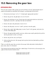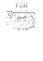
15.5 Removing the gear box
*The drive pipe, up/down shaft, up/down gear, pinion B block, arm (left, right) and guide roller F
cannot be disassembled or assembled if the massager is not dismounted from the chair.
1. Perform removal of steps 1 to 10 of " 3. Removing the tapping shaft assembly ".
2. Remove the gear box side guide plate set screws N and O.
3. Remove the transformer set screw R, and remove the transformer and remove the base for
transformer set screw R-1, and remove the base for transformer.
4. Remove the motor side guide plate set screws S to U.
5. Remove the idler pulley set screws V and W, and remove the idler pulley.
6. Remove the eccentric link holding plate set screws X and Y with a spanner, and remove the
eccentric link holding plate.
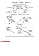
7. Remove the tapping shaft assembly as one unit, without removing the guide plate for gear box
and the guide plate for motor. (see Figure)
8. Remove the gear box screws (see Figure)
9. After removing the screws, the massage clutch, up/down clutch and intermediate gear block
can be removed.
*Take care so that the grease does not stick to the massage clutch and up/down clutch pulleys. If
grease sticks, remove it with alcohol.
*The massage clutch and up/down clutch have similar shapes. The lead wires are the same gray color,
so please choose based on connector color.
Summary of Contents for EP790-C1
Page 2: ... TOP NEXT ...
Page 4: ... TOP PREVIOUS NEXT ...
Page 8: ... TOP PREVIOUS NEXT ...
Page 10: ... TOP PREVIOUS NEXT ...
Page 15: ...4 1 PARTS IDENTIFICATION TOP PREVIOUS NEXT TOP PREVIOUS NEXT ...
Page 16: ...4 2 TURNING ON THE POWER TOP PREVIOUS NEXT ...
Page 17: ...TOP PREVIOUS NEXT ...
Page 18: ...5 Required tools TOP PREVIOUS NEXT ...
Page 19: ...TOP PREVIOUS NEXT ...
Page 20: ...6 Simplified wiring diagram TOP PREVIOUS NEXT ...
Page 21: ... TOP PREVIOUS NEXT ...
Page 26: ......
Page 32: ... TOP PREVIOUS NEXT ...
Page 35: ... TOP PREVIOUS NEXT ...
Page 39: ... ...
Page 40: ...TOP PREVIOUS NEXT ...
Page 43: ... TOP PREVIOUS NEXT ...
Page 54: ...TOP PREVIOUS NEXT ...
Page 56: ......
Page 57: ... TOP PREVIOUS NEXT ...
Page 61: ...15 7 Assembling TOP PREVIOUS NEXT 15 7 1 Assembling the oval gear TOP PREVIOUS NEXT ...
Page 63: ... TOP PREVIOUS NEXT ...
Page 65: ... TOP PREVIOUS NEXT ...
Page 67: ... TOP PREVIOUS NEXT ...
Page 71: ...TOP PREVIOUS NEXT ...
Page 73: ... TOP PREVIOUS NEXT ...
Page 74: ...16 Arranging massage block lead wires TOP PREVIOUS NEXT ...
Page 75: ...TOP PREVIOUS NEXT ...
Page 76: ...17 Actual wiring diagram TOP PREVIOUS NEXT ...
Page 77: ... TOP PREVIOUS NEXT ...
Page 78: ...18 Trouble shooting TOP PREVIOUS NEXT ...
Page 79: ......
Page 80: ......
Page 81: ......
Page 82: ... TOP PREVIOUS NEXT ...
Page 86: ...19 3 Q A TOP PREVIOUS NEXT TOP PREVIOUS NEXT ...
Page 88: ...20 EXPLODED VIEW TOP PREVIOUS NEXT TOP PREVIOUS NEXT ...
Page 95: ......
Page 96: ......


