Installation, Use and Maintenance Manual - ERV+DX series
page 26
En
g
lis
h
SECtIoN 4 - ElECtrICal CoNNECtIoNS
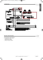
• The electrical connections to the control cabinets must be carried out by specialized staff, following the supplied wiring diagrams.
• Make sure that the voltage and the frequency specified on the nameplate correspond to those of the power supply line.
• For the main supply of the regenerator is not allowed to use adapters, multiple sockets and/or cable extensions.
• the installer must foresee the installation of the cut-off switch and of everything that is necessary for the protection of the electri-
cal components, as close as possible to the unit.
• Connect the unit to an effective earth, using the appropriate screw fitted on the unit.
Before beginning whichever operation make sure that the voltage supply is cut off.
Carry out the connection with cables of a section which is adapted to the engaged power and in the respect of the local norms. their
dimension must however allow to realize a voltage drop of less than 3% during the starting phase.
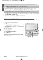
4.1 Installation and servicing of Cz-rtC2 remote controller
4.1.1 Installation of Cz-rtC2 remote controller
• The remote control panel is suitable for wall mounting
• To mount:
- unlock the rear cover (locked by plastic tooth) and fix it to the wall using
the prearranged holes
- lock the main body to the rear cover fixed on the wall
• Connect the two wires to R1-R2 terminals inside the electrical box in the supply
section with DX coil
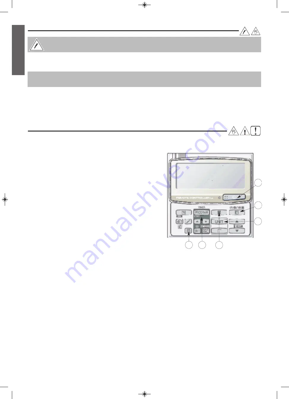
4.1.2 Cz-rtC2 user interface
1 - Switch on/stand-by button
2 - Mode selection button
3 - Fan speed selection button
4 - Unit selection button (in case of multi-machine)
5 - Clock program buttons
6 - Filter check reset button
Instructions for use and setting are explained in the specific manual supplied
together the remote controller.
1
2
3
4
6
5
DC MAN I 00 ERVDX 01 - Man. Inst. CFR microDX - Panasonic_SIC 11/10/2013 8.20 Pagina 26


