3DQDVRQLF
80
25.
C-Board Processing
25.1. Power Supply
2.1. Operation Primary Side
Located on the C-Board is the internal amplifiers for
the Centre, Surround and Super 3D Bass channels.
To perform this internal amplification a separate
power supply is used.
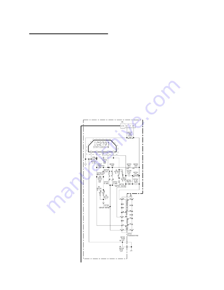
A d.c. voltage of approximately 300V is fed from the
bridge rectifier D801 located on the E-Board, via
connector E5 to the C-Board and connector C1.
Once the d.c. voltage is on the C-Board it is supplied
to the Dolby power supply and the primary winding
P2/P1 of Transformer T2701 and
IC2701
pin 3.
The rectified voltage is stabilised by a parallel switch
mode power supply comprising of
IC2701
and
T2701,
IC2701
containing a switching and stabilising
circuit.
The power supply starting current is fed via resistors
R2702 and R2703 to
IC2701
pin 2, which causes Q3
(
IC2701
) to turn ON causing a rising current to flow
through P2, P1 via pin 3, pin 4 and R2709.
The current flowing through winding P2.P1 will
continue to rise until a saturation point is reached, at
which point no more positive voltage is fed back to
IC2701
pin 2, the polarity of the charge on C2711
becomes such that pin 2 goes negative switching
OFF Q3. This causes the magnetic field built up in
winding P2.P1 to collapse, transferring the stored
energy to the secondary side producing the required
voltages.
Summary of Contents for EURO 4 Chassis
Page 24: ...3DQDVRQLF 24 ...
Page 26: ...3DQDVRQLF 26 TV STANDARDS ...
Page 93: ...3DQDVRQLF 10 ...
Page 97: ...3DQDVRQLF 14 Chapter 2 EURO 4 Supplement P Board DAF Circuit ...
Page 101: ...3DQDVRQLF 18 ...
Page 121: ...3DQDVRQLF 38 Chapter 3 EURO 4H Supplement Y Board Schematic ...
Page 124: ...3DQDVRQLF 41 ...


