9
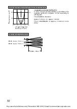
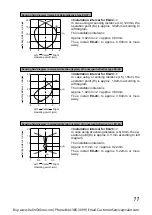
3-4 Installation interval
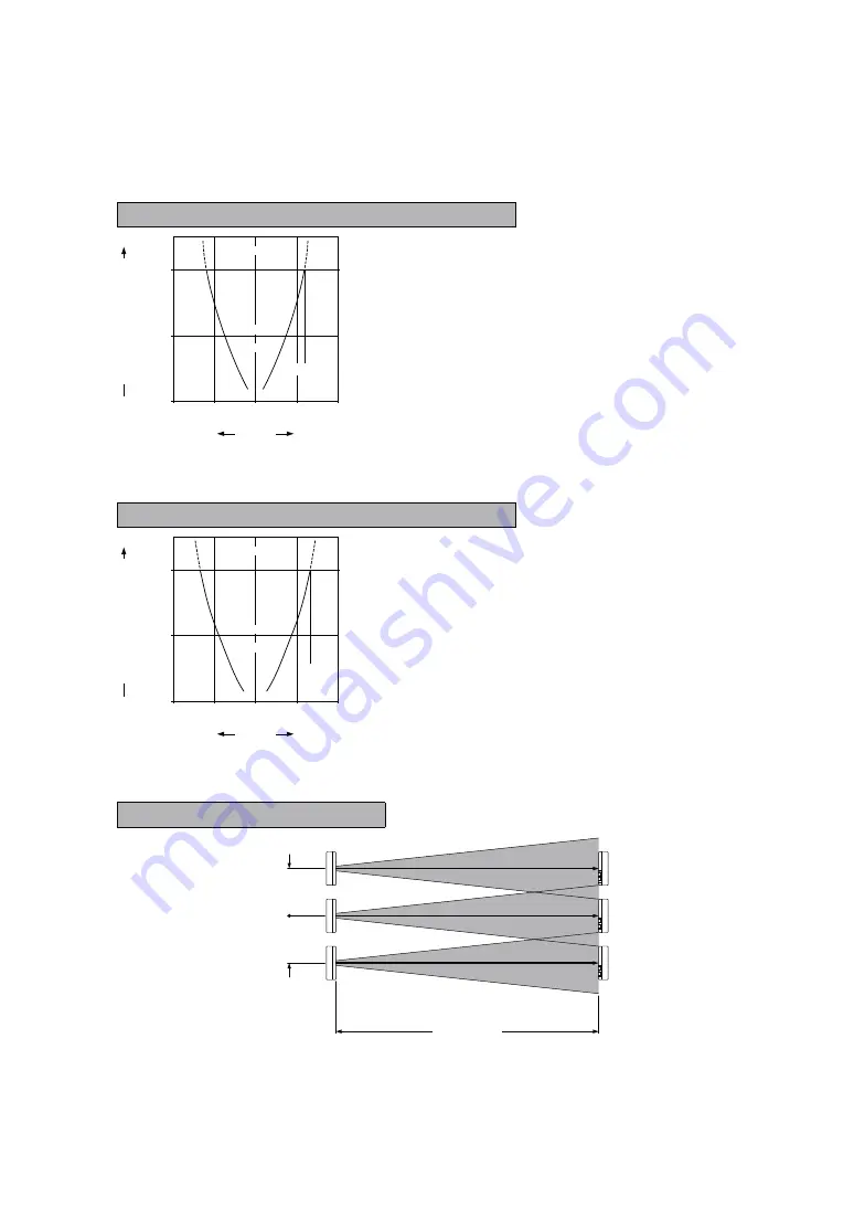
+ This product does not incorporate auto interference prevention function. In case aligning
2 of this sensors closely, follow diagrams below. (typical)
+ R W X'
< $ Y W '
6799%9':
In case using at sensing distance (L1) 1m, the op-
WZ\ @' ^_'$
diagram.
The installation interval is
Approx. 59.2mm × 2 = approx. 118.4mm
Thus, install
EX-21
: @' ZZ&'{
away.
6799%9' :
In case using at sensing distance (L2) 2m, the op-
W$\ @' ||'_
diagram.
The installation interval is
Approx. 66.9mm × 2 = approx. 133.8mm
Thus, install
EX-23
: @' ZQQ'&
away.
EX-21
:K }@' ZZ&'{
EX-23
:K }@' ZQQ'&
EX-21
:K Z
EX-23
:K $
EX-21
:K }@' ZZ&'{
EX-23
:K }@' ZQQ'&
Parallel deviation diagram (typical) of Thru-beam type EX-23
:
100
W$\
50
0
50
100
1
2
(L2)
0
Setting distance L
(mm)
Center
Left
Right
W \
Parallel deviation diagram (typical) of Thru-beam type EX-21
:
100
WZ\
50
0
50
100
0.5
1
(L1)
0
Setting distance L
(mm)
Center
Left
Right
W \
Buy: www.ValinOnline.com | Phone 844-385-3099 | Email: CustomerService@valin.com


