


Leak Detection Sensor
EX-F70
SERIES
EX-F60
SERIES
860
FIBER
SENSORS
LASER
SENSORS
PHOTO-
ELECTRIC
SENSORS
MICRO
PHOTO-
ELECTRIC
SENSORS
AREA
SENSORS
LIGHT
CURTAINS
PRESSURE /
FLOW
SENSORS
INDUCTIVE
PROXIMITY
SENSORS
PARTICULAR
USE
SENSORS
SENSOR
OPTIONS
SIMPLE
WIRE-SAVING
UNITS
WIRE-SAVING
SYSTEMS
MEASURE-
MENT
SENSORS
STATIC
CONTROL
DEVICES
ENDOSCOPE
LASER
MARKERS
PLC /
TERMINALS
HUMAN
MACHINE
INTERFACES
ENERGY
CONSUMPTION
VISUALIZATION
COMPONENTS
FA
COMPONENTS
MACHINE
VISION
SYSTEMS
UV
CURING
SYSTEMS
Selection
Guide
Wafer
Detection
Liquid Leak
Detection
Liquid Level
Detection
Water
Detection
Color Mark
Detection
Hot Melt Glue
Detection
Ultrasonic
Small / Slim
Object Detection
Obstacle
Detection
Other
Products
SQ4
EX-F70/
EX-F60
PRECAUTIONS FOR PROPER USE
Refer to General precautions.
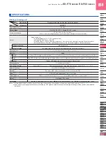
Operation
Connection
state of
the leak
detection
sensor
State of the
connection
setting
switch
Leak
detected
condition
Normal
indicator
(Green)
Error
indicator
(Red)
Output
indicator
(Orange)
Normal
Connected
ON
Not
leaked
Lights
up
Turns
off
Lights
up
Leaked
Turns
off
Lights
up
Turns
off
Unconnected
OFF
―
Turns
off
Turns
off
Lights
up
Error
Connected
OFF
Not
leaked
Lights
up
Lights
up
Turns
off
Unconnected
ON
―
Turns
off
Lights
up
Turns
off
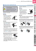
EX-FC1
Connection setting switch
• The connection setting should be carried out in the power
supply off condition after removing any electrostatic charge
which may be present on your body.
• For the channel that the unit sensor is connected to and
the connection setting switch is set to “ON” side, the error
indicator (red) lights up for a moment when the power is
turned on. This is not a malfunction for the unit because it
is caused by characteristic of the sensor.
• Make sure to set the connection setting switch with the
connector No. to which the leak detection sensor is
connected, to “ON” side.
• In case both the normal indicator (green) and the error
indicator (red) light up, the connection setting switch with
the connector No. to which the leak detection sensor is
connected, is not set to “ON” side. Set the connection
setting switch with the connector No. to which the leak
detection sensor is connected, to “ON” side.
• In case the error indicator (red) lights up, the leak
detection sensor detects leak or the connection setting
switch is set to “ON” side without connecting the leak
detection sensor. If the connection setting switch is set to
“ON” side without connecting the leak detection sensor,
set the connection setting switch to “OFF” side.
• If the leak detection sensor detects leak or the connection
setting switch is set to “OFF” side in the state that the
leak detection sensor is improperly mounted to the
mounting bracket, the sensor judges as the output is ON.
Be careful when setting.
All models
Wiring
• Make sure that the power supply is off while wiring.
• Verify that the supply voltage variation is within the rating.
Take care that if a voltage exceeding the rated range or
an AC power supply is directly applied, the sensor may get
damaged or burnt.
• If power is supplied from a commercial switching regulator,
ensure that the frame ground (F.G.) terminal of the power
supply is connected to an actual ground.
• In case noise generating equipment (switching regulator,
inverter motor,etc.) is used in the vicinity of this product,
connect the frame ground (F.G.) terminal of the equipment
to an actual ground.
• Do not run the wires together with high-voltage lines or
power lines or put them in the same raceway. This can
cause malfunction due to induction.
• Make sure to use an isolation transformer for the DC power
supply. If an auto-transformer (single winding transformer)
is used, this product or the power supply may get damaged.
• In case a surge is generated in the used power supply,
connect a surge absorber to the supply and absorb the
surge.
• Cable extension is possible up to total 50 m
164.05 ft
with
0.3 mm
2
, or more, cable (less than 10 m
32.81 ft
for
EX-FC1
). However, in order to reduce noise, make the
wiring as short as possible.
• Make sure that stress by forcible bend or pulling is not
applied directly to the sensor cable joint.
•
EX-FC1
output dose not incorporate a short-circuit
protection circuit.
Do not connect it directly to a power supply or a capacitive
load.
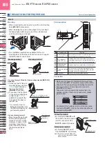
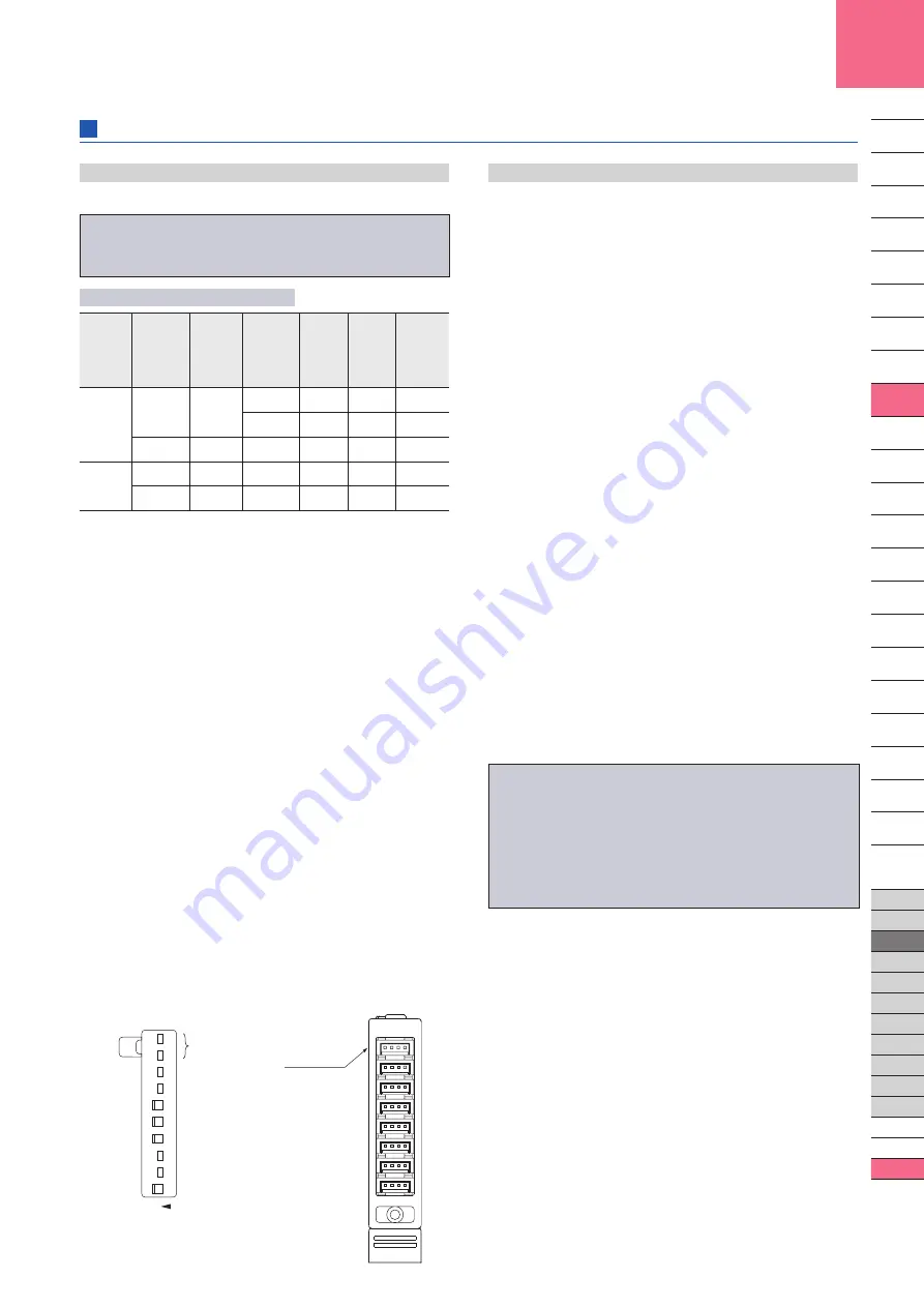
( )
7
6
5
4
3
2
1
0
7
NOT
USED
6
5
4
3
2
1
0
ON
Connector No.
These are not used.
“ON” side
“ON” side
“ON” side
“ON” side
Connection setting switch setting example
In case the input of 0, 3, 4 and 5 are set
to effective.
• In case air bubbles are drawn into the sensing part, take
care that it may take some time for sensing to stabilize, or
sensing may even become unstable.
Check the usage conditions thoroughly before use.
• Do not use during the initial transient time (leak detection
sensor: 50 ms approx.,
EX-FC1
: 0.5 sec. approx.) after
the power supply is switched on.
• Since this sensor employs non-modulated infrared LED,
take sufficient care against extraneous light. Do not
expose the sensing part directly to the extraneous light.
• Avoid dust, dirt, and steam. Further, do not use this
product in an environment containing organic solvents.
• Take care that
EX-7□(-PN)
and
EX-FC1
does not come
in contact with oil, grease or organic solvents, such as,
thinner, etc.
• In case this sensor is used where electrostatic charge
is present, use a metal leak pan, which should be
connected to an actual ground.
• These sensors are only for indoor use.
• Avoid using the product in an explosive atmosphere
because this product does not have an explosive-proof
protective construction.
• When liquid remains on the sensing surface after leak
detection, wipe all liquid from the sensing surface. To
avoid scratching the sensing surface and the enclosed
mounting bracket, use a soft cloth.
Others
Operation matrix for each indicator


