


861
Leak Detection Sensor
EX-F70
SERIES
EX-F60
SERIES
FIBER
SENSORS
LASER
SENSORS
PHOTO-
ELECTRIC
SENSORS
MICRO
PHOTO-
ELECTRIC
SENSORS
AREA
SENSORS
LIGHT
CURTAINS
PRESSURE /
FLOW
SENSORS
INDUCTIVE
PROXIMITY
SENSORS
PARTICULAR
USE
SENSORS
SENSOR
OPTIONS
SIMPLE
WIRE-SAVING
UNITS
WIRE-SAVING
SYSTEMS
MEASURE-
MENT
SENSORS
STATIC
CONTROL
DEVICES
ENDOSCOPE
LASER
MARKERS
PLC /
TERMINALS
HUMAN
MACHINE
INTERFACES
ENERGY
CONSUMPTION
VISUALIZATION
COMPONENTS
FA
COMPONENTS
MACHINE
VISION
SYSTEMS
UV
CURING
SYSTEMS
Selection
Guide
Wafer
Detection
Liquid Leak
Detection
Liquid Level
Detection
Water
Detection
Color Mark
Detection
Hot Melt Glue
Detection
Ultrasonic
Small / Slim
Object Detection
Obstacle
Detection
Other
Products
SQ4
EX-F70/
EX-F60
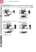
EX-F71
(
-PN
)
EX-F72
(
-PN
)
Sensor
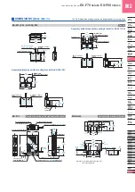
Assembly dimensions with mounting bracket for EX-F71
(
-PN
)
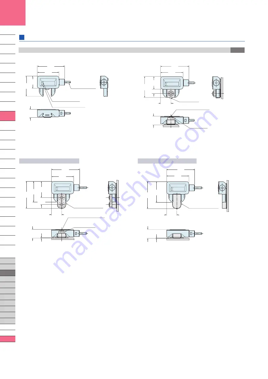
Assembly dimensions with mounting bracket for EX-F72
(
-PN
)
MS-EX-F7-3 / For two-point-fixing
MS-EX-F7-2 / For adhesive fixing
Note: A M4 stud-bolt has been welded to this unit.
M4 nut is not supplied with the sensor.
Purchase it separately.
Note: M4 stud-bolts have been welded to this unit.
M4 nuts are not supplied with the sensor.
Purchase it separately.
26.5
1.043
16
0.630
35.9
1.413
28.5
1.122
10.7
0.421
ø2.5
ø0.098
cable,
2 m
6.562 ft
long
FAULT indicator (Red)
NORMAL indicator (Green)
28.5
1.122
16
0.630
26.5
1.043
5.5
0.217
13
0.512
11
0.433
35.9
1.413
(Straight type)
M4 (length 10 mm
0.394 in
)
stud-bolt (Note)
M4 nut (Note)
MS-EX-F7-1
)
(
SUS mounting
bracket
26.5
1.043
0.5
0.020
35.9
1.413
28.5
1.122
34.7
1.366
9
0.354
20.7
0.815
11.2
0.441
13
0.512
2-M4 nuts (Note)
)
(
(Straight type)
2-M4 (length 10mm
0.394 in
)
stud-bolts (Note)
PVC mounting bracket
for two-point-fixing
MS-EX-F7-3
26.5
1.043
0.5
0.020
35.9
1.413
28.5
1.122
34.7
1.366
11.2
0.441
13
0.512
MS-EX-F7-2
)
(
PVC mounting bracket
for adhesive fixing
DIMENSIONS (Unit: mm
in
)
The CAD data in the dimensions can be downloaded from our website.


