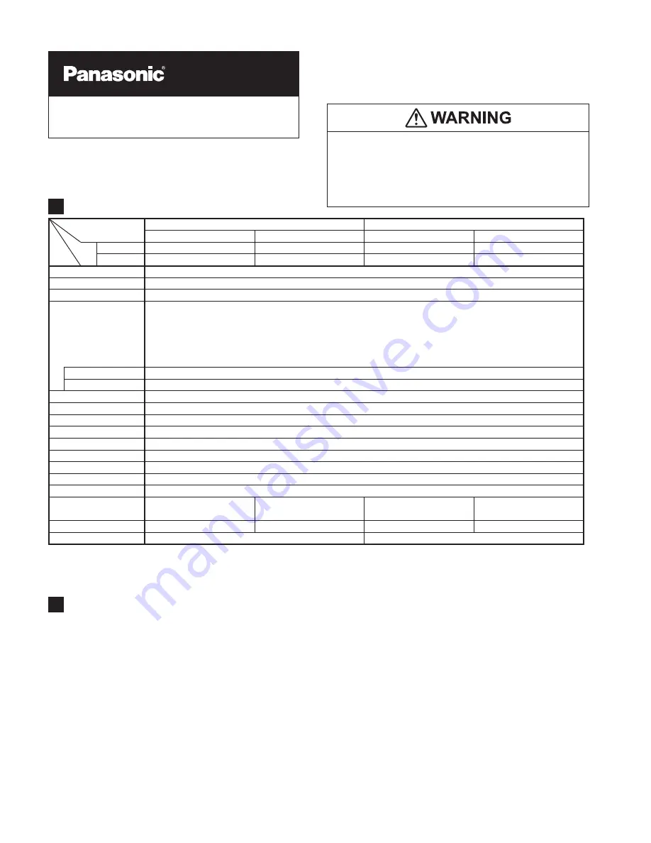
SPECIFICATIONS
1
Notes: 1) Highly viscous liquid may not be stably detected.
2) Fluorinert
TM
is the worldwide trademark of 3M.
3) Liquid being detected should be also kept within the rated ambient temperature range.
Type
SUS mounting bracket type
PVC mounting bracket type
2m cable length type
5m cable length type
2m cable length type
5m cable length type
Model NPN output
EX-F71
EX-F71-C5
EX-F72
EX-F72-C5
Item
No. PNP output
EX-F71-PN
EX-F71-PN-C5
EX-F72-PN
EX-F72-PN-C5
Sensing object
Water, Fluorinert
TM
(Note 1) (Note 2)
Supply voltage
12 to 24V DC ± 10% Ripple P-P 10% or less
Current consumption
10mA or less (PNP output type: 15mA or less)
Output
<NPN output type>
NPN open-collector transistor
Maximum sink current: 50mA
Applied voltage: 30V DC or less (between output and 0V)
Residual voltage: 1.0V or less (at 50mA sink current)
0.4V or less (at 16mA sink current)
<PNP output type>
PNP open-collector transistor
Maximum source current: 50mA
Applied voltage: 30V DC or less (between output and +V)
Residual voltage: 1.0V or less (at 50mA source current)
0.4V or less (at 16mA source current)
Output operation
ON when normal operation, OFF when leak is detected or the sensor is mounted improperly.
Short-circuit protection
Incorporated
Response time
50ms or less
Abnormal indicator
Red LED (lights up when leak is detected or the sensor is mounted improperly.)
Normal indicator
Green LED (lights up when the sensor is mounted properly.)
Protection
IP67 (IEC)
Ambient temperature
–10 to +60°C (No dew condensation or icing allowed) (Note 3), Storage: –20 to +70°C
Ambient humidity
35 to 85% RH, Storage: 35 to 85% RH
Ambient illuminance
Incandescent light: 1,000
Ɛ
x or less at the light-receiving face
Emitting element
Infrared LED (non-modulated)
Material
Enclosure: Polypropylene
Cable
0.1mm
2
3-core PVC
cabtyre cable, 2m long
0.1mm
2
3-core PVC
cabtyre cable, 5m long
0.1mm
2
3-core PVC
cabtyre cable, 2m long
0.1mm
2
3-core PVC
cabtyre cable, 5m long
Weight
Approx. 25g
Approx. 55g
Approx. 25g
Approx. 55g
Accessories
SUS mounting bracket: 1 pc.
PVC mounting bracket: 1 pc. each for two-point-
¿
xing and adhesive-
¿
CAUTIONS
2
Ɣ
This product has been developed / produced for
industrial use only.
Ɣ
Av o i d u s i n g t h e p r o d u c t i n a n e x p l o s i v e
atmosphere because this product does not have
an explosive-proof protective construction.
Ɣ
Make sure that the power supply is off while wiring.
Ɣ
Take care that wrong wiring will damage the sensor.
Ɣ
Verify that the supply voltage variation is within
the rating.
Take care that if a voltage exceeding the rated
range is applied, or if an AC power supply is directly
connected, the sensor may get burnt or damaged.
Ɣ
If power is supplied from a commercial switching
regulator, ensure that the frame ground (F.G.)
terminal of the power supply is connected to an
actual ground.
Ɣ
Do not use during the initial transient time (approx.
50m sec. ) after the power supply is switched on.
Ɣ
In case noise generating equipment (switching
regulator, inverter motor, etc.) is used in the vicin-
ity of this product, connect the frame ground (F.G.)
terminal of the equipment to an actual ground.
Ɣ
Cable extension is possible up to total 50m with
0.3mm
2
, or more, cable. However, in order to re-
duce noise, make the wiring as short as possible.
Ɣ
Do not run the wires together with high-voltage lines
or power lines or put them in the same raceway.
This can cause malfunction due to induction.
Ɣ
In case a surge is generated in the used power sup-
ply, connect a surge absorber to the supply and ab-
sorb the surge.
Ɣ %
e sure to use the exclusive mounting bracket when installing
the sensor to avoid human error, etc. Reliable detection can-
not be guaranteed when this mounting bracket is not used.
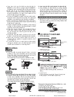
MOUNTING
3
(;)Ƒ
Ɣ
Insert the M4 stud-bolt (length 10mm or more)
welded on the user’s facilities into the mounting
hole of the SUS mounting bracket and screw with
an M4 nut (please arrange separately).
The tightening torque should be 0.98N·m or less.
M4 nut
<Mounting dimensions (Unit: mm)>
M4 stud-bolt
(straight type)
26.5
16
13
5.5
(;)Ƒ
,QFDVHRIXVLQJWKHWZRSRLQW¿
xing PVC mounting bracket>
Ɣ
Insert M4 stud-bolts (length 10mm or more) welded
on the user’s facilities into the mounting holes of
the two-point-fixing mounting bracket and screw
with M4 nuts (please arrange separately).
The tightening torque should be 0.49N·m or less.
M4 nuts
M4 stud-bolts
(straight type)
<Mounting dimensions (Unit: mm)>
26.5
34.7
13
9
20.7
How to
¿
t the sensor body to the exclusive mounting bracket
<In case of using the PVC mounting bracket for adhesive
¿
xing>
Ɣ
Use adhesive to stick fast the mounting bracket
on the mounting surface. Please note that if the
adhesive sticks out from the bottom surface of
the mounting bracket or is 0.5mm, or more thick,
the sensor body cannot be
¿
tted to the mounting
bracket.
Ɣ
Match the notch in the sensor body with the
projection of the exclusive mounting bracket and
slide till a click is felt.
Notch
Projection
I/O CIRCUIT DIAGRAMS
4
Ɣ
NPN output type
Ɣ
PNP output type
Load
Internal circuit
Users’ circuit
(
%
rown) +V
(
%
lue) 0V
50mA max.
(
%
lack) Output
12 to 24V DC
±10%
+
-
Color code
Main circuit
Load
Internal circuit
Users’ circuit
(
%
rown) +V
(
%
lue) 0V
50mA max.
(
%
lack) Output
12 to 24V DC
±10%
+
-
Color code
Main circuit
INTENDED PRODUCTS FOR CE MARKING
5
Ɣ
The models listed under “ SPECIFICA-
TIONS” come with CE Marking.
As for all other models, please contact our
of
¿
ce.
Ɣ
Take care not to use the SUS mounting bracket for
EX-F72
Ƒ
or the PVC mounting bracket for EX-F71
Ƒ
mistakenly, since normal detection cannot be performed.
Ɣ
Make sure to use an isolation transformer for the
DC power supply. If an auto-transformer (single
winding transformer) is used, this product or the
power supply may get damaged.
Ɣ
In case air bubbles are drawn into the sensing part,
take care that it may take some time for sensing to
stabilize, or sensing may even become unstable.
Ɣ
When conducting maintenance after operation,
wipe all liquid from the sensor and mounting
bracket with a soft cloth.
Ɣ
If there is liquid remained or scratch on the sensing
surface or the exclusive mounting bracket, normal
operation cannot be performed.
Ɣ
Since this sensor employs non-modulated infrared
LED, take suf
¿
cient care against extraneous light.
Do not expose the sensing part directly to the
extraneous light.
Ɣ
Avoid dust, dirt, and steam. Further, do not use this
product in an environment containing organic solvents.
Ɣ
Take care that the product does not come in
contact with oil, grease or organic solvents, such
as, thinner, etc.
Ɣ
In case this sensor is used where electrostatic
charge is present, use a metal leak pan, which
should be connected to an actual ground.
Thank you very much for purchasing Panasonic products.
Please read this Instruction Manual carefully and thor-
oughly for the correct and optimum use of this product.
Kindly keep this manual in a convenient place for quick reference.
Ɣ
Never use this product as a sensing device for
personnel protection.
Ɣ
In case of using sensing devices for personnel protec-
tion, use products which meet laws and standards, such
as OSHA, ANSI or IEC etc., for personnel protection ap-
plicable in each region or country.
INSTRUCTION
MANUAL
Ampli
¿
er
%
uilt-in Leak Detection Sensor
EX-F70 Series
MJEC-EXF71 No.0044-45V
http://panasonic.net/id/pidsx/global
Overseas Sales Division (Head Of
¿
ce)
2431-1 Ushiyama-cho, Kasugai-shi, Aichi, 486-0901, Japan
Phone: +81-568-33-7861 FAX: +81-568-33-8591
About our sale network, please visit our website.
© Panasonic Industrial Devices SUNX Co., Ltd. 2014
PRINTED IN JAPAN
Ɣ
Contact for CE
Panasonic Marketing Europe GmbH Panasonic Testing Center
Winsbergring 15, 22525 Hamburg,Germany
Ramco National
800-280-6933 | nsales@ramcoi.com
www.panasonicsensors.com


