background image

4

3.1.

Trial Operation (after checking Troubleshooting Guide.)

3.1.1.

ASSEMBLY

• Confirm if there is NO gap between Housing A and B by pinching the lead wires.
• Confirm if there is NO deformation on the battery terminals.
• Confirm all screws are tightened firmly.

3.1.2.

Operation

• Check if the switch turns ON and OFF smoothly.
• Check if the blade strokes properly.
• Cut concrete panel <(t) 12mm X (w) 300mm> as trial.
• Check if there is no metallic sound, abnormal sound or abnormal vibration.
• Check the speed control and braking.
• Confirm if the LED lights on.

Summary of Contents for EY4550

Page 1: ...iolation of law Order Number PTD1105E39CE Cordless Jigsaw Model No EY4550 Europe TABLE OF CONTENTS PAGE PAGE 1 Warning 2 2 Specifications 2 3 Troubleshooting Guide 3 4 Disassembly and Assembly Instructions 5 5 Wiring Connection Diagram 9 6 Schematic Diagram 9 7 Exploded View and Replacement Parts List 10 ...

Page 2: ...ng point is 50 70 F 30 40 C higher Please use a soldering iron with temperature control and adjust it to 750 20 F 400 10 C In case of using high temperature solder ing iron please be careful not to heat too long Pb free solder will tend to splash when heated too high about 1100 F 600 C 2 Specifications ...

Page 3: ...3 3 Troubleshooting Guide Refer to Wiring Connection Diagram ...

Page 4: ...ere is NO deformation on the battery terminals Confirm all screws are tightened firmly 3 1 2 Operation Check if the switch turns ON and OFF smoothly Check if the blade strokes properly Cut concrete panel t 12mm X w 300mm as trial Check if there is no metallic sound abnormal sound or abnormal vibration Check the speed control and braking Confirm if the LED lights on ...

Page 5: ...t the dust cover 2 Wipe away any cutting dust from the blade and the blade clamp bracket 3 Pull the blade Attach Remove lever 4 Pull out the blade CAUTION Be careful to avoid cutting your hands on the blade Ref No 1B Procedure 1A 1B Removal of base 1 Use the provided hex wrench to loosen the hexagon socket screw NOTE Keep the hex wrench in the storage slot on the tool s body when not using it 2 Re...

Page 6: ...Ref No 1D Procedure 1A 1B 1C 1D Removal of driving assembly 1 Take out the driving assembly together with the switch assembly 2 Loosen 4 screws to disassemble the motor assembly for reassembly If the fan baffle is pulled out NOTE Make sure to attach the fan baffle otherwise the pendulum pin may not work NOTE Make sure to attach the hexagon nut on the rear side of fan baffle ...

Page 7: ...tape to fix the lead wires NOTE Make sure to place the switch without pinching the lead wires over the rib of housing Ref No 1F Procedure 1A 1B 1C 1D 1E 1F Removal of control PCB Removal Pull out the connector from the module assembly NOTE Make sure to hold the connector at the bottom area Assembly 1 Apply the permalub grease around the tactswitch and connectors NOTE Make sure to apply the grease ...

Page 8: ...irmly 2 Insert the LED into the hole of gear box block until all the way back NOTE Make sure the lead wires are not pulled back when placing them in the housing rib 3 Place the LED lead wires properly If failure to do it may short circuited with the radiating plate 4 Close the housing A and B ...

Page 9: ...9 5 Wiring Connection Diagram 6 Schematic Diagram ...

Page 10: ...Model No EY4550 Exploded View 7 Exploded View and Replacement Parts List ...

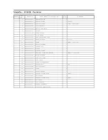
Page 11: ...0K2008 SWITCH ASSEMBLY 1 13 WEY4550L2128 CONTROL PCB 1 14 WEY4550L0968 O RING 1 15 WEY4550H1558 BLOWING LEVER 1 16 WEY4550L6258 PAN HEAD SCREW WITH WASHER 4 M4X20 4PCS PK 17 WEY4550L1008 MOTOR ASSEMBLY 1 18 WEY4550L1458 GEAR CASE BLOCK 1 19 WEY4550X3108 DUST COVER 1 20 WEY4550L0228 LEVER FIXING BRACKET 1 21 WEY4550K6378 HEXAGON NUT 1 M5 22 WEY4550S1898 BASE ASSEMBLY 1 23 WEY4550K0258 CLAMP 1 24 WE...

Reviews: