background image

ORDER NO. PTD1408E44CE 


TABLE OF CONTENTS 

Impact driver 

Model No. 

EY7530 

Europe 

Panasonic corporation  2014.  
All rights reserved. Unauthorized copying and distribution 
is a violation of law. 

PAGE 

1. Warning 

2


2. Specifications 

3. Troubleshooting Guide 

4. Disassembly and Assembly Instructions 

5. Wiring Connection Diagram 

10 

6. Schematic Diagram 

10 

7. Exploded View and Replacement Parts List  

  11 

Summary of Contents for EY7530

Page 1: ...ation 2014 All rights reserved Unauthorized copying and distribution is a violation of law PAGE 1 Warning 2 2 Specifications 2 3 Troubleshooting Guide 3 4 Disassembly and Assembly Instructions 6 5 Wiring Connection Diagram 10 6 Schematic Diagram 10 7 Exploded View and Replacement Parts List 11 ...

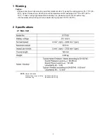
Page 2: ...higher Please use a soldering iron with temperature control and adjust it to 750 20 F 400 10 C In case of using high temperature soldering iron please be careful not to heat too long Pb free solder will tend to splash when heated too high about 1100 F 600 C NOTE Weight indication Greater than or equal to 1kg indicated by 0 05kg Less than 1kg indicated by 0 01kg ...

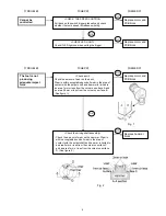
Page 3: ...block CHECK MOTOR AND PCB BLOCK After attaching the battery pack removing the tool housing and removing the motor and gear case block pull the trigger and check whether the motor operates CHECK TERMINAL CONNECTIONS BETWEEN MAIN UNIT AND BATTERY PACK There are no much gull Terminal connections are not blackened and allow conduction Terminal connections are not rusty or deformed Replace motor and PC...

Page 4: ...pact force Check anvil Check the amount of wear on the anvil Wear is within acceptable bounds if wear in the area of contact with the output shaft and hammer is limited to an area 1mm or less from the corner on surface A and an area 0 5mm or less from the corner on surface B See figure 1 Check the driving shaft assembly Check the amount of wear on the hammer Wear is within acceptable bounds if wea...

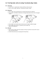
Page 5: ...res directions Check whether the LED light illuminates when the trigger depressed and turns off when the trigger is released Check whether the tool speed increases continuously as the trigger is gradually engaged Check whether the tool speed is normal after repair and reassembly Speed 2700 RPM approx 3 3 3 Integrity With the switch activated shake the tool back and forth and up and down and verify...

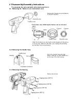
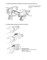
Page 6: ...ecorate cover and fixation cover from main tool Attach the fixation cover aligning the protruding part with the groove on the housing Attach the decorate cover aligning the protruding part with the notch on the housing Pull on the handle hoop with a flat blade screwdriver or other suitable tool and remove it from the housing Remove ten screws Precautions when attaching the fixation cover and decor...

Page 7: ... 4 4 Removing the Motor and PCB block F R selector handle and LED cover 4 5 Removing the driving block and anvil from motor Remove the F R selector handle LED cover and motor and PCB block from housing A ...

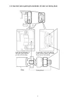
Page 8: ...arding the installation of motor and driving block Align the protruding part of the motor mount with the groove on the housing Orienting the notch on the bearing so that it faces forward align it with the groove on the housing ...

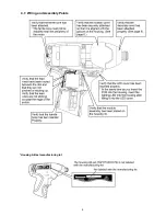
Page 9: ...9 4 7 Wiring and Assembly Points Housing AB set manufacturing lot ...

Page 10: ...10 5 Wiring Connection Diagram Omitted due to use of blocks 6 Schematic Diagram Omitted due to use of blocks ...

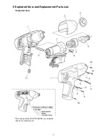
Page 11: ...11 5 Exploded View and Replacement Parts List Exploded View The housing AB set WEY7530H3078 is not labeled with the manufacturing lot ...

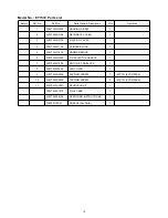
Page 12: ...VER 1 4 WEY7530L1128 SPINDLE BLOCK 1 5 WEY7530L1618 HAMMER BLOCK 1 6 WEY7530H3248 F R SELECTOR HANDLE 1 7 WEY7530L1008 MOTOR PCB BLOCK 1 8 WEY7530L0548 LED COVER 1 9 WEY7430K9038 TAPPING SCREW 7 M3 16 8PCS PACK 10 WEY7530K9038 TAPPING SCREW 3 M3 12 3PCS PACK 11 WEYFLA1AL007 HANDLE HOOP 1 WEY7530K7018 TOOL CASE 1 WEY7530K8108 OPERATING INSTRUCTIONS 1 WEY001T8907 GREASE ALVANIA 1 ...

Reviews: