- 11 -
• When the main unit is held by the belt
hook, avoid jumping or running with it.
Doing so may cause the hook to slip and
the main unit may fall.
This may result in an accident or injury.
• When the belt hook is not used, be sure
to return it to the storing position. The belt
hook may catch on something.
This may result in an accident or injury.
• When the unit is hooked onto the waist belt
by the belt hook, do not attach driver bits to
the unit. A sharp edge object, such as a drill
bit, may cause injury or an accident.
To Change the Belt Hook
Location Side
The belt hook can be attached to either side
of the unit.
1. Removing the hook
(1) Remove the nut.
(2) Draw out the hook.
2. Attaching the hook to the other side
(1) Insert the hook in the other side.
(2)
Tighten the nut fully so that it securely
fastened.
Variable Speed Control Trigger
To set the center of a hole, pull the trigger
slightly to start the bit rotation slowly.
The more the speed control trigger is
pulled, the higher the speed becomes.
CAUTION:
When operating the tool by pulling the
trigger, there may be a momentary lag
before rotation starts. This does not signal
a malfunction.
• This lag occurs as the tool’s circuitry
starts up when the trigger is pulled for
the first time after installing a new bat-
tery pack or after the tool has not been
used for at least 1 minute (or at least 5
minutes when the LED is on). Rotation
will start without any lag during second
and subsequent operations.
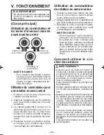
Control Panel
(1)
(2)
(4) (3)
(1) Impact Power Mode Select
Selecting the impact power among 3
modes (Soft, Medium, Hard).
Press the impact power mode button
to set it. The mode changes to hard,
medium, or soft each time the button is
pressed.
The driver is preset to “hard” impact mode
setting when shipped from the manufac-
turer.
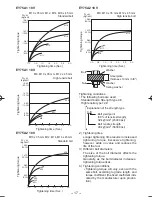
Recommended work guideline table
Impact
Power mode
Display
Recommended Application
H
Jobs requiring a high level
of torque where there is
no possibility of the screw
breaking, its top shearing off,
or the bit coming loose. (This
setting provides maximum
torque.) Suitable applications
include:
Tightening M8 and larger
bolts
Tightening long screws
during interior finishing work
0 – 2300 r.p.m./
0 – 2500 r.p.m.
and
0 – 3000 i.p.m./
0 – 3500 i.p.m.
M
Jobs requiring limited torque
where there is a possibility of
the screw breaking or its top
shearing off. (This setting limits
torque.) Suitable applications
include:
Tightening bolts with
smaller diameters (M6)
Tightening metalwork
screws when installing
fixtures
0 – 1400 r.p.m.
and
0 – 2800 i.p.m.
S
Jobs requiring limited torque
where there is a possibility
of the screw breaking, its
top shearing off, or the bit
coming loose and damaging
a fi nished exterior surface.
(This setting limits torque.)
Suitable applications include:
Tightening bolts smaller
than M6 that may shear
easily
Tightening screws into
molded plastic
Installing gypsum wallboard
0 – 1000 r.p.m.
and
0 – 2000 i.p.m.
EY7546_EY7547_EY7550_EY7551_US.indb 11
EY7546_EY7547_EY7550_EY7551_US.indb 11
2012-10-10 10:17:44
2012-10-10 10:17:44
Summary of Contents for EY75A1X
Page 55: ... 55 MEMO ...
Page 56: ...EN FR ES EY981075A11 2012 10 Printed in China ...


