12
5 Disassembly and Assembly Instructions
5.1.
Disassembly Instructions
Ref. No. 1A
Procedure 1A
Removal of the Housings.
1. Remove four screws where tightening fixation cover.
2. Pull off the fixing cover assembly.
3. Once removing the fixing cover, the driving shaft assembly may come
out.
Ref. No. 1B
Procedure 1A
1B
Removal of bit holder.
(EYFLA4A and EYFLA5A only)
1. Remove C-type ring by the stop ring pliers.
2. Once removing C-type ring, thrust plate, bit holder spring, bit holder
and steel balls may come out.
Summary of Contents for EYFLA4AR
Page 3: ...3 3 Troubleshooting Guide ...
Page 4: ...4 ...
Page 5: ...5 ...
Page 6: ...6 4 Service Fixture and Adjustment 4 1 Check Parts Identify Procedure ...
Page 7: ...7 ...
Page 8: ...8 ...
Page 24: ...24 7 Wiring Connection Diagram ...
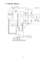
Page 25: ...25 8 Schematic Diagram ...
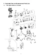
Page 26: ...26 9 Exploded View and Replacement Parts List 9 1 EXPLODED VIEW for EYFLA4AR ...
Page 28: ...28 9 3 EXPLODED VIEW for EYFLA5AR ...
Page 30: ...30 9 5 EXPLODED VIEW for EYFLA5QR ...


