13
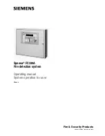
Operation Manual
FT1020G3 Rev 2.10.4
2
General Description
2.1
The FT1020G3 FDCIE
FT1020G3
is a microprocessor controlled intelligent fire alarm system, intended for
analogue addressable detectors, as well as conventional detectors and manual call points.
Four loops are available to connect addressable units e.g. On each COM loop it is possible
to connect up to four SUB-loops.
Programmable control outputs and output units are available.
Up to 1012 addresses can be connected to each FT1020G3. Figure 1 below presents an
overview of the FT1020G3 system.
Programmable control outputs and output units are available.
FT1020G3
is available in several types e.g. large FT1020G3L and small FT1020G3S,
cabinets, versions and configurations. It can be used as a standalone FDCIE or connected
to a TLON network, i.e. in a "system", with up to 30 Control Units. Each Control Unit has
access to all information.
FT1020G3
is designed and assessed to the Australian Standard AS7240.2, AS7240.4 and
NZS4512:2010. The Fire Brigade Panel controls are incorporated as part of the front fascia
and conforms to AS4438.3.
Figure 1 Connection diagram of FT1020G3
Note:
Some units are not available for the Australian market e.g. exit emergency light
MX140, aspirating unit AE2010G-P. other units are currently not approved e.g. 4466, 4585,
4464, etc.
Technical Number
The technical number, NNNNNN, is used when programming all units connected to the
COM loops. Technical number is also used to identify which unit has generated a fault. See
section 7.1, page 47.
Presentation Number
Each fire alarm point / input / zone has a presentation number, NNN-NN. The presentation
number is shown in the FDCIE display to identify the point / zone activating fire alarm. See
section 7.2, page 47.
1202
1201
1203
Summary of Contents for Firetracker FT1020G3 CIE
Page 1: ...Operation Manual FT1020G3 Rev 2 10 4 For Software V2 10 4 FT1020G3 FDCIE MA430 March 2023...
Page 2: ...This page has deliberately been left blank...
Page 176: ...176 Operation Manual FT1020G3 Rev 2 10 4 Figure 24 FT1020G3 Standard Block Wiring Diagram...
Page 177: ...177 Operation Manual FT1020G3 Rev 2 10 4 Figure 25 FT1020G3 New 5012 PCB Layout...


