background image

4-69

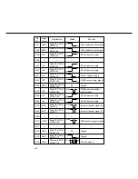
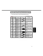
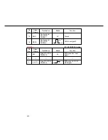
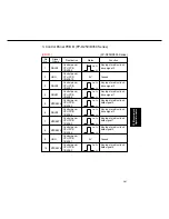
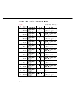
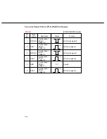
PCB Connector and

Signal Information

Status

0V

Pin

No.

Signal

Name

Destination

Function

3.3V

0V

71

72

A0

GND

16 M Flash
DIMM PCB
CN351-71

16 M Flash
DIMM PCB
CN351-72

Flash memory address
bus signal

Ground

Summary of Contents for FP-D350

Page 1: ...on FP D450 D600 1 17 5 Sensor Location 1 18 6 Solenoid Clutch Discharge lamp Location 1 19 7 PCB Location FP D250 D350 D350H 1 20 8 PCB Location FP D450 D600 1 20 9 Hard Disk Drive Zip Drive Location 1 21 1 8 Copy Process 1 22 1 9 Precautions with Consumables 1 23 1 10 Digital Image Control Qualitative Reasoning Based Adaptive Controller 1 25 II Sub Assemblies 2 1 Main Drive 2 1 2 2 Operation 2 2 ...

Page 2: ...nt 3 43 3 Skew Side to side Adjustments Printer Section 3 44 4 Skew Registration Adjustments Scanner Section 3 46 5 Lead edge Trail edge void adjustment Printer Section 3 47 6 Laser power PWM circuit 3 48 IV PCB Connector and Signal Information 4 1 Glossary of electrical abbreviations 4 1 4 2 Main CPU PCB FP D250 D350 Series 4 7 4 3 System Control PCB FP D250 D350 Series 4 53 4 4 Control Panel PCB...

Page 3: ... PCB FP D450 D600 Series 4 205 1 Control Panel CPU PCB FP D450 D600 Series 4 205 2 Control Panel PCB A FP D450 D600 Series 4 211 3 Control Panel PCB B FP D450 D600 Series 4 215 4 Control Panel PCB C FP D450 D600 Series 4 216 5 Control Panel PCB D FP D450 D600 Series 4 218 4 20 CCD PCB FP D450 D600 Series 4 219 4 21 SO DIMM PCB FP D450 D600 Series 4 222 4 22 16 M Flash DIMM PCB FP D450 D600 Series ...

Page 4: ... 4 Program Update 5 87 1 Update procedure of the printer controller SIMM 5 87 VI Unpacking Installation 6 1 Precautions on Set Up 6 1 6 2 Unpacking 6 2 6 3 Installation Procedure 6 3 6 4 Adjustment 6 10 6 5 Printer Unit DD Filing Unit Mounting kit FA PK30 6 13 6 6 Printer Unit FA PC350 Multi PDL Controller FA MC350 6 19 6 7 Network Adapter Card for Ethernet FA NE35 6 22 6 8 Hard Disk Driver for Pr...

Page 5: ...radio communications Operation of this equipment on a residential area is likely to cause harmful interference in which case the user will be required to correct the interference at his her own expense Any unauthorized changes or modifications to this equipment would void the users authority to operate this device For U S A This manual was developed and is supplied to authorized servicing dealers ...

Page 6: ... laser radiation when open Avoid direct exposure to beam Rayonnement laser invisible si ouvert Dangereux de regarder a l interieur Unsichtbare laserstrahlen wenn geöffnet Nicht hinensehen Peligro Cuando la cubierta esté abierta se podrá escapar radiación de rayo láser Evite la exposición directa al rayo láser FFPTE DANGER Invisible laser radiation when open and interlock defeated AVOID DIRECT EXPO...

Page 7: ...A OLET ALTTIINA LASERSATEIL YLLE ALA KATSO SATEESEN VORSICHT Unsichtbare Laserstrahlung wenn Abdeckung geoffnet und Sicherheitsverriegelung uberbruckt NICHT DEM STRAHL AUSSETZEN ATTENTION Rayonnement laser invisible dangereux en cas d ouverture et lorsque la securite est neutralisee EXPOSITION DANGEREUSE AU FAISCEAU PELIGRO Cuando se abre y se invalida el bloqueo se producen radiaciones invisibles...

Page 8: ... ske med batteri af samme fabrikat og type Lever det brugte batteri tilbage til leverrandoren CAUTION Danger of explosion if battery is incorrectly replaced Replace only with the same or equivalent recommended by the manufacturer Dispose of used batteries according to the manufacturer s instructions For Holland Batterij niet weggooien maar inleveren als KCA NL Caution Danger of explosion if batter...

Page 9: ...HOCK IF THE CUT OFF PLUG IS INSERTED INTO ANY 13 AMP SOCKET If a new plug is to be fitted please observe the wiring code as shown below If in any doubt please consult a qualified electrician WARNING THIS APPLIANCE MUST BE EARTHED IMPORTANT The wires in this mains lead are coloured in accordance with the following code Green and Yellow Earth Blue Neutral Brown Live As the colours of the wires in th...

Page 10: ...50 D350 Series 550 sheet 1 FP D450 D600 Bypass 50 sheets Copy size Ledger A3 Invoice A5 Paper exit tray capacity 250 sheets Ambient conditions Temperature 50 86 F 10 30 C Relative humidity 30 80 Noise level Stand by 32 dB Operation 49 dB FP D250 D350 series 54 dB FP D450 D600 Warm up time Approx 75 sec FP D250 D350 series Approx 180 sec FP D450 D600 Power consumption Less than 1 4 kW FP D250 D350 ...

Page 11: ...ith Auto mode FA D250 D350 series 4 0 sec Letter A4 size with Auto mode FA D450 3 5 sec Letter A4 size with Auto mode FA D600 Copy ratio Enlargement fixed North America 2 00 1 55 1 29 1 21 Europe others 2 00 1 73 1 41 1 22 1 15 Reduction fixed North America 0 79 0 77 0 65 0 61 0 50 Europe others 0 87 0 82 0 71 0 58 0 50 Zoom 25 400 1 step Copy speed D250 D350 series D450 D600 Ledger A3 18 CPM 20 C...

Page 12: ...perating system Windows 3 1 North America Windows 95 Windows 98 Windows NT 4 0 MacOS 7 5 2 8 X MacOS7 5 2 support available with Postscript option Network Specifications Board type Option board connected to printer unit Memory capacity 1 MB Connecting type Ethernet 100 BaseTX 10 BaseT Communications protocol Ethernet TCP IP IPX SPX EtherTalk Operating system Windows 3 1 95 Windows NT4 0 Mac OS Net...

Page 13: ...a chine speed 100 throughput Except for FP D600 3 User friendly operation 1 Bi directional communication touch panel display enables easy operation by simply touching the icon on the wide screen 2 Paper level sensor in the cassette indicates a low paper condition This function prevents no paper condition during the operation 4 Various optional accessories are available for functional expansion 1 O...

Page 14: ...t you get These internal fonts are part of the PCL language 7 Options 1 Expansion memory 16 MB Faster print speed can be expected by speed of rasterrinsing process When the image processing memory of the copier is 8 MB FP D250 All FP D350 except North America If the machine error often occurs when the high density of information document such as gray color A3 size print is being printed even thoug...

Page 15: ... 3 Multi Original Image Rotation If the paper direction in the cassette is different from the direction of the original the image is automatically rotated 90 degrees so that the proper copy is obtained 4 N in 1 copy mode From two or four 1 sided originals side by side to 1 sided copies can be made 5 Wide Zoom Ratio 25 400 Copies can be made from 25 to 400 of the original document size at 1 increme...

Page 16: ...5 3000 Sheet Cassette FA MA301 Paper drawer Kit FA DK10 Printermemory 32MB FA PM32 Printer Memory 16MB FA PM16 PCL5e Printer Unit FA PC350 PC Server Network Adapter Card Multi Page Description Language Controller PCL5e PS II FA MC350 7 7 DD Browser Software FA WB10 DD Server Software FA WS10 ZIP Drive EtherNet FA NE35 FA WA01 For FP D250 D350 D350H FA WA02 For FP D450 D600 1 4 System Configuration...

Page 17: ...5 FA MA301 FA UC20 FA GK35 FA A355 FA A888 FFPTL0277 FFPTL0323 FFPTL0324 FA X350 FA F350 FA F355 FA F320 FA FK35 FA RU350 FA TR355 FA TR350 FA DM08 FA DM16 FP D250 D350 Remarks Kit required for FA MA0555 installation in bottom slot of FA DS725 Available through parts route This kit is required when installing FA A888 North America Available through parts route This kit is required when installing ...

Page 18: ...lable through parts route For North America Available through parts route For Europe Available through parts route For North America Available through parts route For Europe Available through parts route Available through parts route This kit is required when installing printer unit 8MB 2GB Expansion memory limited to 16 MB or 32 MB Except for North America and Europe 10 100 base TX 20 000 copies ...

Page 19: ...sonal Card DD Browser Software DD Server Software Hard Disk Drive for Back up DD filing Accessories Remarks For FA WA01 WA02 Model Number FP D450 D600 FP D350H FP D250 D350 Model number FA WA01 FA WA02 FA KP01 FA WB10 FA WS10 FA HD02 Standard Standard ...

Page 20: ... D350 D450 D600 USER PRESET MULTI SIZE FEED SORT FINISH INTERRUPT MANUAL ENERGY SAVER RESET CLEAR STOP START TOUCH PANEL DISPLAY ORIGINAL SIZE COPY SIZE Ready Indicator Ready GreenLED Not ready RedLED Copy Reservation FIashing OPERATION SWITCH D450 D600 USER PRESET ORIGNAL SIZE COPY SIZE MULTI SIZE FEED SORT FINISH ADVANCED FUNCTIONS ADDPAPER ONLINE DATA DOCUMENT SAVE INTERRUPT MANUAL ENERGY SAVER...

Page 21: ...PLAY RESET CLEAR STOP START ADVANCED FUNCTIONS COPY ORIGINAL SIZE COPY SIZE Ready Indicator Ready GreenLED Not ready RedLED Copy Reservation FIashing USER PRESET ORIGNAL SIZE COPY SIZE MULTI SIZE FEED SORT FINISH ADVANCED FUNCTIONS ADDPAPER ONLINE DATA DOCUMENT SAVE INTERRUPT MANUAL ENERGY SAVER RESET CLEAR STOP START c 9 1 2 6 5 4 7 8 0 3 OPERATION SWITCH D450 D600 ...

Page 22: ...aper drawer tray Paper drawer tray or ADU Automatic duplex unit Option FP D250 D350 D350H Standard FP D450 D600 Paper exit door Control panel Power switch D450 D600 inside of front door Platen cover option Zip Drive Option FP D250 D350 D450 D600 Standard FP D350H Operation Switch D450 D600 ...

Page 23: ...bottle 3 Drum unit 4 Developer unit 5 Toner hopper unit 6 Developer release lever 7 Waste toner bottle 8 Total counter 9 Manual paper feed knob Feed unit 10 Paper transport handle 11 Transfer Separation corona 12 Paper transport unit 13 Manual paper feed knob Fuser unit SV711 ...

Page 24: ...17 DFP roller 18 Pick up roller 19 ADU Paper feed roller 20 Transport Separation corona 21 Drum 22 Transport belt 23 Pressure roller 24 Fuser lamp 25 Fuser separation finger lower 26 ADU guide roller 27 Fuser separation finger upper 28 Paper exit roller 29 Paper exit sensor 30 Heat roller 31 Cleaning web roller 32 Full speed unit home position sensor 1 32 31 30 29 28 27 26 25 24 23 22 20 19 18 17 ...

Page 25: ... motor ADU paper width guide motor ADU drive motor Optics fan Main motor Exhaust fan Lifting motor lower stage Lifting motor upper stage Suction Ozone fan Included with the ADU unit Option and Printer unit Option FP D250 D350 Standard FP D350H Developer Unit cooling fan Printer controller cooling fan Power supply cooling fan ...

Page 26: ...Dust collecting fan Optics fan Main motor Exhaust fan Lifting motor lower stage Suction Ozone fan Included with the Printer unit Option Developer Unit cooling fan Printer controller cooling fan Power supply cooling fan ADU drive motor ADU paper length guide motor ADU paper width guide motor ...

Page 27: ...detection ADU paper pass 2 Registration roller paper pass Paper detection lower stage Paper limit lower stage Middle roller paper pass upper lower stage Waste toner bottle Total counter Bypass paper detection Bypass paper size Toner level Toner bottle home position Paper feed cover open close Included with the ADU unit Option FP D250 D350 D350H Standard FP D450 D600 Paper level upper stage D250 D3...

Page 28: ...lower stage Paper exit solenoid Power switch Door switch ADU clutch Pick up solenoid lower stage Recycle solenoid Included with the ADU unit Option FP D250 D350 D350H Standard FP D450 D600 Laser unit switch Paper feed speed control clutch Separation solenoid FP D450 D600 Operation Switch D450 D600 Paper feed clutch Pick up solenoid upper stage D250 D350 D350H ...

Page 29: ...C driver CCD control Control panel D Control panel C Printer controller option NAC 8 PCB Location FP D450 D600 LVPS Low voltage power supply Image Processing CPU Automatic duplex unit driver Option Control panel B Touch panel Control panel CPU Control panel A HVPS High voltage power supply AC driver CCD control Control panel D Control panel C Printer controller option NAC option Printer Controller...

Page 30: ...Introduction 1 21 9 Hard Disk Drive Zip Drive Location Zip drive Hard disk for filing Hard disk for printer Option Hard disk for back up Option Option FP D250 D350 D450 D600 Standard FP D350H ...

Page 31: ...ely 750V DC Charge corona Drum Latent charge image Illumination Magnetic roller Bias 550 V Latent charge image Discharge lamp Heat roller Fuser lamp Paper Pressure roller Latent image Transfer Charge DC Cleaning blade Drum Toner Paper Separation Charge AC Photo electric conversion DC AC Aluminium layer Fuser temperature approximately 190 C D250 D350 D350H approximately 180 C D450 D600 Image Option...

Page 32: ... adding toner or developer in the developer unit discard what was spilled Such supplies may damage the drum as well as cause other trouble with the image 3 Do not place into other containers Toner and developer must not be placed into other containers because some containers may change the characteristics of the supplies Vinyl chloride potentially changes the characteristics of supplies because of...

Page 33: ...ff with soapy water Toner stuck on clothing must be removed in a dry condition by a vacuum cleaner brush or beating and then washed with soapy water Wiping off with benzine alcohol or thinner is not recommended because it may partially melt the components of toner resulting in a stain and spot Toner spilled must be removed with a vacuum cleaner and then wiped with a cloth which has been dampened w...

Page 34: ...oning Based Adaptive Controller In this way it finds the optimum compensation values to tighten the gamma curve by changing laser power and grid voltage for maintaining peak copy quality The control of the gamma curve stabilizes copy quality by monitoring two points of copy quality medium density and black density and has a direct effect on background solid area density and good reproduction of fi...

Page 35: ...ion of copy density are used one for halftone line pattern and one for black density The system provides a measured amount of light and detects the reflected light The resultant value is used for sensor compensation This becomes the reference value As the reference value of gamma curve changes various components are automatically adjusted by the machine F mode F6 80 Automatic compensation value re...

Page 36: ...shading Scaner data Image density Sensor mark sheet Black level Sensor mark sheet CCD electrical adjustment CCD High density Middle density Density data from printer Image Density ID White Black Digital QUANTUM QUARC Control LSU Electronic Pattern Laser power Grid Voltage Copy density sensor Scanner Printer ...

Page 37: ...e Density Density data from printer 255 0 0 35 1 25 Image Density ID Electronic Pattern Halftone Black Halftone sensor Copy density sensor Sensor Output Drum Black sensor Halftone Black Grid Voltage Laser Power Laser Unit Digital QUANTUM QUARC Control ...

Page 38: ...hotoreceptor drum Developer unit paper feed unit paper transport unit fuser unit and paper exit unit Optics motor Pulse control Optics system scanning and return Paper feed unit Lower stage Middle roller Paper feed unit Middle roller Registration roller Bypass unit Pulley 2 Pulley 1 Main motor Magnetic roller Drum Transport roller Fuser unit Middle gear Flywheel Middle roller clutch ...

Page 39: ...stration roller 7 Paper pass sensor Detects paper just before registration roller 8 Cleaning sheet Prevents paper dust from sticking to both registration rollers 2 2 Operation 1 Sheet bypass paper feed 1 Construction of the sheet bypass paper feed unit The construction of the sheet bypass paper feed unit consists of a sheet bypass paper feed roller transfer roller paper pass sensor DFP roller and ...

Page 40: ...ied time the sheet bypass clutch turns off which stops the sheet bypass feed rollers When the sheet bypass solenoid turns off the transfer roller is lifted up The paper is held in place by the registration roller After a specified time following the optics system start the lamp unit home position sensor detects the passing of the optics system full speed unit the registration roller clutch is turn...

Page 41: ...bypass paper size The paper size for the sheet bypass is detected by a matrix of sheet bypass paper size sensors which are installed on the sheet bypass tray When setting the paper in the sheet bypass tray and adjusting the paper guide the matrix is as follows S1 S2 S4 Middle roller upper Middle roller lower Sheet bypass unit Middle gear Main motor Pulley 2 Pulley 1 Middle roller clutch Clutch Mid...

Page 42: ...per feed solenoid Lowers the paper transfer roller to the paper 4 Paper feed clutch Drives paper feed unit 5 Paper pass sensor Detects the paper passage 6 Middle roller Drives the paper to machine 7 Double feed Prevents double paper feed prevention roller 8 Paper detecting sensor Detects the paper in paper feed cassette 9 Paper level upper limit sensor Detects the upper limit position when lifting...

Page 43: ...prevention roller is under specific torque When multiple sheets are fed the double feed prevention roller rotates in the reverse direction feeding the bottom paper back into the drawer The paper pass sensor checks the paper feed from the drawer If the paper is not detected by the paper pass sensor within a specified time the Retry system is employed The paper arrives at the middle roller and is de...

Page 44: ...per feed unit turns on and the revolution of the lift motor stops to keep the paper at the specific position 4 Detecting paper The paper detecting sensor is turned ON if there is any paper in the drawer If there is no paper in the drawer the paper detecting sensor is turned off by the actuator falling into the groove in the drawer bottom plate As paper is used the drawer bottom plate is lifted up ...

Page 45: ...he developer on the sleeve forms a brush by the magnetic force of the magnetic roller and makes contact with the electrostatic latent image on the drum Toner is attracted to the areas of the drum which have been discharged by the laser The doctor blade regulates the height of the magnetic brush which is formed by the developer which is attracted to the sleeve of the magnetic roller The TDC sensor ...

Page 46: ...d by the transport screw and the mixing mill The toner becomes negatively charged and the carrier becomes positively charged The developer is magnetically attracted to the aluminum sleeve of the magnetic roller and the magnetic brush is formed The magnetic roller sleeve rotates in a counterclockwise direction The height of magnetic brush is controlled by the gap between the doctor blade and the sl...

Page 47: ...ise the head of the developer and controls the head height via the doctor blade N2 through S1 Transfers the developer to the developing position N1 through N2 Separates the developer from the sleeve 3 Driving developer The revolution of the main motor is transmitted to the developer drive gear via the respective drive gears and belt The developer unit receives drive from the main motor by the resp...

Page 48: ...ling removing the developer unit Turning the Developer Release Lever clockwise rotates the Cam releasing the pressure between the Magnetic roller spacer and the Drum spacer Accordingly the Developer Unit is released from the Drum ...

Page 49: ...nsor output voltage than the standard The lower density of toner causes the increase of TDC sensor output Being over the standard the toner hopper motor drives and toner is supplied to the developer mixing unit to keep the toner density consistent Change of toner density and change of TDC sensor output voltage Amount of carrier passing TDC sensor Toner density condition Sensor output voltage Less ...

Page 50: ...ensor for every copy the timing of toner supply to the developer unit is controlled so that the output voltage is 2 5V the at all times keeping the toner density constant Supply toner from reserve tank for 6 7 seconds amount of toner supply approx 0 4 1 2 g Rotate bottle for 7 seconds toner to reserve tank Toner is not supplied to developer unit Check TDC sensor output voltage at copying or mixing...

Page 51: ... Developer Unit Sensor output Gain adjustment Sensor Area 3 Vp TDSN TDREF GND Vp TDSN CN3 TDREF GND 2 4 1 7 8 6 9 Reference 1 Toner supply route Reference 2 Forced toner supply Reserve tank hopper Developer unit Bottle Supply toner supply for 6 7 seconds from reserve tank amount of toner supply approx 1 1 g Rotate bottle for 7 seconds supply toner to reserve tank Toner is not supplied to developer...

Page 52: ...nd the waste toner bottle respectively Usually the aperture to the recycle unit is opened The toner transferred with the toner transport coil spring falls down through this hole and is transferred to the developer mixing unit by the recycle screw When the machine is in the Refresh mode the recycle solenoid actuates and the toner is transferred to the waste toner screw and is sent to in the waste t...

Page 53: ...ring toner in toner hopper supply to developer mixing unit 4 Toner volume sensor Detect toner level in reserve tank 5 Hopper motor Drive toner bottle and toner supply roller 6 Toner supply roller Supply toner to developer mixing unit 7 Toner supply shutter Prevents accidental toner dropping when developer mixing unit is separated from the toner supply unit Bottle holder Sensor plate Supply roller ...

Page 54: ... Reserve Tank to the Developer Mixing Unit This direction is controlled by the TDC Sensor Toner supplied by the toner supply roller varies from 0 4 to 1 2 grams of toner depending toner density When the developer mixing unit is separated from the toner supply unit of the toner hopper the toner supply shutter is closed to prevent accidental toner dropping TDC sensor output Toner volume Hopper Toner...

Page 55: ...will be disabled after approximately 300 copies This feature is dependant on the settings of F5 59 63 The Add toner indication is cleared by replacing the toner bottle 4 Detecting the toner bottle position Insert the toner bottle in the hopper and turn to the specified position Accordingly the toner bottle shutter opens and is able to add toner to the hopper The bottle home position sensor which i...

Page 56: ...resh mode the undesirable particles are removed from the developer unit and forwarded to the waste toner bottle to be discarded Control Approximately every 2 000 copies FP D250 D350 Series 500 copies FP D450 D600 the toner recycle system activates the toner recycle solenoid switching the machine from the recycle mode to the refresh mode The machine will remain the refresh mode for the next 300 cop...

Page 57: ...eparate from photo receptor Transport drive gear 3 5 4 5 Paper transport unit and separation unit 1 Paper transport unit The paper transport unit transports the paper after transfer separation The paper is secured by the suction fan and transferred to the fuser via the transfer belt The paper transport unit is driven by the main motor which transfers drive to the paper transport drive gear via res...

Page 58: ... the heat roller and control temperature to a specified level 7 Main heater lamp Halogen lamp for fusing 8 Sub heater lamp Lighting warming up faster FP D450 D600 9 Fuser inlet guide Guides paper to fuser roller 10 Upper fuser separation finger Assists in separating the copy paper from the heat roller 11 Lower fuser separation finger Assists in separating the copy paper from the pressure roller 12...

Page 59: ... the specified value The fuser thermostat which is installed on top of the heat roller protects the fuser unit from overheating The pressure roller is composed of silicone rubber which is covered with a fluorine plastic tube to enhance the durability of the roller The pressure roller applies pressure provided by the fuser pressure springs to the heat roller to from a nip width contact area which p...

Page 60: ...he cleaning web composed of rolled unwoven cloth impregnated with silicone oil supplies silicone oil to the heat roller to prevent the offset of toner and markings onto the copy The heat roller transfers oil to the pressure roller through normal contact The cleaning web is driven by the heat roller drive gear via the reduction gear and is advanced very slowly during the copy cycle The cleaning web...

Page 61: ...r turns on and the heat roller and the pressure roller rotate When the surface temperature reaches 190 C the main motor turns off The copier is now in the ready condition c While in the ready condition the thermistor maintains the specified temperature by instructing the CPU PCB to turn the heat lamp on and off Note If the temperature of the heat roller surface does not reach the specified value i...

Page 62: ...450 D600 When 2 sided copying is selected paper exiting the fuser unit will be redirected to the ADU via the paper exit selection guide The guide is activated by the exit solenoid mounted on the rear frame of the copier Paper exit selection guide ADU guide roller Solenoid Paper exit roller ...

Page 63: ...ected through the lens and put on the CCD image sensor which converts light signals into electric signals When the light signals are converted into electronic signals the image of the original is changed to an electronic signal of the picture element which corresponds to image density This electronic signal analog signal is converted to digital signal by the CCD control PCB then sent to image proc...

Page 64: ...image sensor Converts light into electronic signals 9 Exposure lamp Xenon lamp which illuminates the original 2 The process of converting light into electric signals is called photo electric conversion The elements used for the photo electric conversion are called photo electric conversion elements which use a reduced type of mono chrome linear CCD sensor 3 CCD sensor CCD image sensor consists of ...

Page 65: ...rol signal LPCNT1 of the main CPU PCB is at L level the exposure lamp Xenon lamp is turned on at a high frequency by the lamp inverter Main CPU PCB Lamp inverter Exposure lamp Xenon lamp LPCNT1 Lamp inverter control signal LPCNT1 Lamp inverter control signal OFF ON ...

Page 66: ... original to the lens is kept constant The full speed unit is positioned at the lamp home position by the full speed unit position detecting plate and the lamp unit home position sensor The full speed unit holds the exposure lamp and the No 1 mirror It scans the original with the exposure lamp forwards the reflected light to the No 3 mirror via No 1 and No 2 mirrors The image is reflected onto the...

Page 67: ... formation is realized on the drum surface as several 42 3 micron light spots The light spot scans lowered main scan direction in the figure while the image is exposed on the drum as it rotates in the arrow direction sub scan to form a latent electrostatic image Part of the polarized laser beams fall on a synchronization sensor so that timing for image recording start by the laser beams on the dru...

Page 68: ...s divergent light of the semiconductor laser to parallel light so that scanning is stabilized and light spot convergence is improved 4 Polygon scanner The polygon scanner consists of 6 sided pillar shaped rotary mirrors that convert the laser beam into a scanning beam In regard to the performance of high resolution recording the uneven speed of scanning lines reflected from each mirror face the di...

Page 69: ... 42 micron 6 Synchronization signal detector synchronization sensor To accurately detect the position of the laser beam in the main scan direction during drum scanning and to minimize positioning deviation of the image on adjacent scanning lines it is positioned just before drum face scanning during the scan of each face of the polygon scanner to detect laser beam transit timing Polygon scanner mi...

Page 70: ...home position sensor 6 Paper pass sensor 7 Paper detecting sensor 8 Paper weight lever 9 Pinch roller 10 Transfer guide 2 11 Transfer guide 1 12 Paper feed roller 13 Storage roller 14 Paper weight lever 15 Drive motor 16 Magnetic clutch 17 Clutch gear 18 Paper width guide motor 19 Paper length guide motor 20 DFP pad 21 DFP roller 22 Sensor lever 23 Paper feed tray 24 Transfer roller 25 Paper lengt...

Page 71: ...turns clutch gear 4 the lift cam rotates and lifts lift plate 2 by a pressure spring Also the lift shaft and lift plate 2 are driven by the movement of the lift plate 2 and the ADU tray rises After lifting up the ADU tray the magnetic clutch turns ON and the paper feed roller rotates counter clockwise for feeding paper into the copier Storage roller Paper feed roller Magnetic clutch Motor pulley D...

Page 72: ...ed paper size Move back 3 mm of selected paper size 6mm play 3 When stack paper Move to the selected paper size for align paper Once for every sheet entering 4 Paper length guide operation When the paper length guide motor rotates and turns timing belt the paper length guide is moved to align paper Operation timing for the paper length guide is shown below 1 When the power Move to Letter R A4R siz...

Page 73: ...n Copy start Move paper width length guide to selected paper size Drive motor rotates forward rotation and magnetic clutch turns ON Storage roller Paper feed roller rotate Paper pass sensor 1 and 2 ON paper detecting sensor ON Paper align operation Once for every paper Paper stack complete YES NO Drive motor rotates reverse rotation and magnetic clutch turns OFF Slip clutch driven to lift ADU tray...

Page 74: ...tlet Note FP D450 D600 only Bofore disconnecting the power cord please open the front door and exit door Before using solvents such as IPA Isopropyl alcohol put on rubber gloves and eye protection 1 Timing Perform the preventive maintenance service in accordance with the chart of preventive maintenance areas listed in the service manual 2 Cleaning of rollers Rollers should be cleaned with water an...

Page 75: ... is completely sealed by a protective housing and an external cover Therefore the laser beam will not stray or leak during photocopier use However when servicing the photocopier take the following precautions 1 Do not insert into the path of the laser any screwdrivers or other tools that have high reflectance properties 2 Before servicing the photocopier take off any watches rings or other metalli...

Page 76: ...y or repair the saved data always save back up data 3 Precautions when the power switch of the digital copier is turned on off Never turn the power switch off while the copier printer DD file or Zip disk is accessed operation or power switch is turned ON within 2 minutes This may cause the damage to the hard disk or Zip disk and the data in the disk may be destroyed If the power switch is turned o...

Page 77: ...ace the disk where the magnetic field is more than 30 Gauss Remove the disk before turning off the power switch of the Digital copier when disk to be removed from the disk drive 6 Precautions for back up battery Chargeable Ni Cd battery 1 When the message of Back up in progress disappears immediately by turning off the power switch without using the hard disk drive and or Zip drive the battery cha...

Page 78: ...re FFPXL05H00 1 Replace at every 80 000 copies Developer FQ ZL20 1 Replace at every 80 000 copies Drum FQ HL20 1 Replace at every 80 000 copies Side seal Front FFPXG51L00 1 Replace at every 80 000 copies Side seal Rear FFPXG50L00 1 Replace at every 80 000 copies Waste toner bottle FFPQA0165 1 X Toner dispersion cover FFPXG13L00 1 X Magnetic roller stopper Front FFPXG06H001 1 X Magnetic roller stop...

Page 79: ... PQ24V8 7WMG1 1 X Transfer Separation corona FFPVL01L01 1 X Corona wire 1 FFPXL04H00 1 Replace at every 80 000 copies Corona wire 2 FFPXL05H00 1 Replace at every 80 000 copies Dust protection filter FFPHJ0049 1 X Drum Separation finger FFPLK0332 1 X ADU Paper feed roller FFPMA0558 1 X Option Paper feed pad FFPKP00821 1 X DFP roller FFPMA0559 1 X F R mylar FFPXD07J004 1 X Storage roller FFPMA0557 2...

Page 80: ... wire FFPXL05H00 1 X Developer FQ ZL20 1 X Drum FQ HL20 1 X Side seal Front FFPXG51L00 1 X Side seal Rear FFPXG50L00 1 X Waste toner bottle FFPQA0165 1 X Toner dispersion cover FFPXG13L00 1 X Magnetic roller stopper Front FFPXG06H001 1 X Magnetic roller stopper Rear FFPXG07H001 1 X Fuser Separation finger Upper FFPLK0230 5 X unit Separation finger Lower FFPLK0231 2 X Thermister FFPBL0015 1 X Fuser...

Page 81: ... FFPHJ0051 1 X Discharge lamp PQ24V8 7WMG1 1 X Transfer Separation corona FFPVL01L01 1 X Corona wire 1 FFPXL04H00 1 X Corona wire 2 FFPXL05H00 1 X Dust protection filter FFPHJ0049 1 X Drum Separation finger FFPLK0332 1 X ADU Paper feed roller FFPMA0558 1 X Option Paper feed pad FFPKP00821 1 X DFP roller FFPMA0559 1 X F R mylar FFPXD07J004 1 X Storage roller FFPMA0557 2 X ...

Page 82: ...t FFPXG51Q60 1 X Side seal Rear FFPXG50Q60 1 X Waste toner bottle FFPQA0165 1 Replace at 60 000 copies Toner dispersion cover FFPXG13L00 1 X Magnetic roller stopper Front FFPXG06H001 1 X Magnetic roller stopper Rear FFPXG07H001 1 X Fuser Separation finger Upper FFPLK0331 5 X unit Separation finger Lower FFPLK0231 5 X Thermister FFPBL0015 1 X Fuser lamp 950W H12V095WN2A 1 X For North America Fuser ...

Page 83: ...ter 5 FFPHJ0056 1 X Discharge lamp PQ24V10WMG1 1 X Transfer Separation corona FFPVL01Q611 1 X Corona wire 1 FFPXL04H00 1 X Corona wire 2 FFPXL05H00 1 X Dust protection filter FFPHJ0049 1 X Drum Separation finger FFPLK0332 1 X ADU Paper feed roller FFPMA0558 1 X FP D250 Paper feed pad FFPKP00821 1 X D350 DFP roller FFPMA0559 1 X D350H F R mylar FFPXD07J004 1 X Option Storage roller FFPMA0557 2 X ...

Page 84: ...3 11 Preventive Maintenance 3 4 Cleaning Method Cleaning method for each PM service visit is shown below 17 24 23 14 19 18 21 9 8 22 27 10 1 2 3 7 4 28 5 6 12 20 11 13 16 15 26 25 27 ...

Page 85: ...with water Cloth with water Use damp cloth Remove toner dust on separation fingers Don t damage separation finger edges Cleaning position Tool solvent Work precaution Developer unit Fuser unit Paper feed unit to be continued Use IPA if toner is stuck on the rollers use sparingly Do not use cotton for cleaning Remove paper dust by brushing it If not replaced at PM cycle high voltage leak may occur ...

Page 86: ...cover 28 Paper feed roller Cleaning position Tool solvent Work precaution Blower brush Cloth with water Vacuum cleaner Cloth with water Neutral detergent Blower brush Glass cleaning paper with IPA Exercise caution when cleaning otherwise the mirror surface may get damaged Clean with soft paper and IPA as required Clean the dust off of the sensors Cloth Blower brush Cloth with water IPA Same as pap...

Page 87: ...ement procedure The replacement procedure of PM parts is as shown below Fuser Unit 3 25 Optics Unit 3 30 Main body 3 36 3 15 Multi feed bypass Paper feed Unit 3 18 3 33 ADU 3 21 Drum Unit Developer Unit Option ADU middle roller unit 3 18 ...

Page 88: ...80K 5 Registration roller 1080K 1080K 1080K bearing 6 Cleaning sheet 600K 600K 600K Item Cycle D250 D350 D450 D350H D600 3 2 1 4 5 6 Caution Magnet clutch Welded point Welded point D cut Hook Hook D cut When removing the magnet clutch push the hook 1 out of the slot and slide the magnet clutch in the direction of arrow 2 in order to avoid damage to welded point damage Side view Front view ...

Page 89: ...ness 4 Remove the bypass tray 1 1 Remove the touch ring 2 Remove the paper stopper 3 Remove the sensor lever 4 Remove the touch ring 5 Remove the pick up roller 6 Remove the touch ring 7 Remove the paper feed roller 2 1 Perform procedure 1 above 2 Open the copier paper feed door 3 Press the DFP roller down then remove touch ring 4 Remove the DFP roller 3 3 2 4 2 7 5 4 1 3 2 4 3 ...

Page 90: ...ve the cleaning sheet on the top cover 3 Remove the registration roller 7 6 1 Remove the top cover Two screws 2 Remove the tension spring X 2 3 Remove the upper registration roller 4 Remove the paper guide plate Two screws 5 Remove the E rings front and rear 6 Remove the drive gear clutch and E ring 7 Remove the right bushing support plate and bushing 1 screw 8 Remove the Lower registration roller...

Page 91: ...18 2 1 3 4 2 Paper feed unit Part name 1 Paper feed roller 120K 120K 120K 2 Pick up roller 120K 120K 120K 3 DFP roller 120K 120K 120K 4 Middle roller 1080K 1080K 1080K Item Cycle D250 D350 D450 D350H D600 ...

Page 92: ...paper feed door 3 Remove the paper feed door link 4 Remove the copier paper feed door Note Move the link to the larger hole and remove 1 2 1 Disconnect the harness of the paper feed unit 2 Remove the paper feed unit 4 screws 3 1 Remove the touch ring 2 Remove the bracket guide 3 Remove paper feed roller 4 Remove the pick up roller 4 2 1 3 1 2 3 2 1 ...

Page 93: ...rm procedures 1 and 2 2 Remove the lower roller cover 2 screws 3 Remove the touch ring 4 Remove the DFP roller 4 5 1 Perform procedures 1 and 2 2 Remove the E ring gear on middle roller 3 Remove the touch ring and bushing 4 Slide and remove the middle roller 3 3 4 2 2 3 4 ...

Page 94: ... 3 Side seal Front 80K 120K 120K 3 Side seal Rear 80K 120K 120K 4 Corona charger 240K 360K 360K 5 Developer 80K 120K 120K 6 Charge corona 80K 120K 120K 7 Toner dispersion 600K 600K 600K cover 8 Magnetic roller 600K 600K 600K stopper Front 9 Magnetic roller 600K 600K 600K stopper Front Item 9 Cycle D250 D350 D450 D350H D600 ...

Page 95: ...n the waste toner bottle cover and remove the bottle 5 Remove the drum unit 1 Press the tabs of the drum unit lid toward arrow mark to remove the lid 1 Remove the cleaning blade tension spring 2 Remove the blade case 1 screw 3 Remove the cleaning blade Note Before replacing the cleaning blade put drum starting powder on the drum surface and cleaning blade lightly and evenly After replacing the cle...

Page 96: ...ar Note Be careful not to touch the surface of the drum 6 1 Remove the side seals Front and Rear 2 Clean the surface of drum unit frame then replace the side seals Front and rear 3 Clean the copy density sensors Adjustment after replacing new drum a Enter the service mode b Select and run F8 14 c Check copy quality and adjust if necessary d Exit the service mode 7 1 Perform procedures 1 and 2 and ...

Page 97: ...TDC sensor before installing new developer Shake the developer bottle and pour it into the developer unit evenly Adjustment after replacing developer a Enter the service mode b Select and run F8 09 c Write the contents of F6 21 and 26 on the memory sheet d Exit the service mode 4 Removal of the developer 2 5 5 Removal of the toner dispersion plate magnetic roller stopper 1 Perform procedures 1 and...

Page 98: ...ng 360K 360K 360K 6 Heat roller gear 600K 600K 600K 7 Thermistor 240K 240K 240K 8 Separation finger upper 120K 120K 480K 9 Separation finger lower 120K 120K 120K 10 Pressure roller 480K 480K 480K 11 Pressure roller bearing 600K 600K 600K 12 Web pressure 1200K roller 13 Fuser entry guide 1200K 1 3 8 9 10 7 2 4 5 6 11 4 Fuser unit Part name Item Cycle D250 D350 D450 D350H D600 13 12 ...

Page 99: ...e fuser unit connector x 2 2 Open the two cable clamp x 2 3 Open the paper exit unit 4 Remove the fuser bracket 3 screws 5 Carefully slide the fuser unit out of the front of the machine 2 1 1 Remove the web ass y bracket screw x 2 2 Slide the web ass y to the right and remove 3 4 1 Remove the bushings 2 screws and rollers x2 2 Install the new web 3 Make sure to remove the slack in the supply rolle...

Page 100: ...mostat blocks Lift the thermostat and slide to the front 3 Remove the pressure screws x 2 4 Remove the roller pressure plates 5 Remove the heat roller 7 1 Remove the heat roller gear bearing insulating bushing and heat roller stopper Note After reassembling and tightening the screws of the pressure springs check the pressure roller for fit 8 SV 6 1 Remove the spring 2 Open the fuser lamp cover 3 R...

Page 101: ...stor 3 9 1 Open the fuser exit door 2 Remove the screws x 2 3 Remove the separation finger upper bracket 4 Remove the separation fingers upper springs 5 Remove the separation fingers upper 10 1 Remove the screw x1 and fuser exit cover pin then remove the exit cover 2 Remove the screws x 2 3 Remove the paper guide 11 SV507 3 2 1 2 1 2 3 4 5 5 1 2 2 ...

Page 102: ...r roller bearings Remove the heat roller refer to step 5 to 7 Remove the upper lower separation finger brackets refer to 10 and 11 Note Mark the current height adjustment to use as a reference during re assembly 1 Remove the screws x 2 2 Remove the entry guide 3 Remove the pressure roller 4 Remove the roller bearing 12 5 5 4 4 1 2 1 3 ...

Page 103: ...ics unit Part name 1 Exposure lamp 720K 720K 720K 2 Filter A 120K 120K 120K 3 Full speed unit drive belt 4 Half speed unit drive belt 5 Optics drive belt Item 2 1 3 4 5 As required Cycle D250 D350 D450 D350H D600 ...

Page 104: ...lled the grounding plate screw must also be removed 5 Remove platen glass with original guide plate 1 Remove lamp stoppers front rear Note A small flat blade screwdriver must be used to remove the lamp holder spring plates 2 1 Open the inverter case 2 screws 2 Disconnect the exposure lamp connector 3 Remove the exposure lamp connector bracket 1 screw 4 Remove the exposure lamp bracket 5 Remove the...

Page 105: ...he front door 2 Remove the slit glass 3 Remove two screws on the original guide plate Note When the conductive platen glass is installed the grounding plate screw must also be removed 4 Remove platen glass with original guide plate 5 Remove the LSU PCB cover 2 screws 6 Remove the lens unit cover 3 screws 2 connectors 1 Remove the laser unit 4 screws 3 connectors Note After replacing new unit laser...

Page 106: ...Maintenance 6 Automatic duplex unit ADU Option Part name 1 Paper feed roller 24K 2 Storage roller 48K 3 F R mylar 24K 4 Paper feed pad 24K 5 DFP roller 24K Item 2 1 5 3 4 Actual number of duplex copies mode F7 09 Cycle ...

Page 107: ...ve the bearing toward the feed rollers 10 Remove the paper feed roller shaft 1 Pull out the ADU until it stops 2 Remove the upper cover 2 screws 3 Open the transport guides 1 and 2 1 2 1 Remove the touch ring Note Remove all of the rollers by sliding them in the direction of arrow 2 Remove the paper feed roller 1 Perform steps 1 through 10 above 2 Take off the F R mylar assembly Note Remove paper ...

Page 108: ...l off the paper feed pad and replace 5 1 Remove the touch rings x 2 2 Remove the bearing 3 Remove the roller shaft 4 Remove the DFP roller Note When installing the DFP roller the marked edge should face the front of the machine 1 Perform procedure 1 2 Remove the screws x 2 3 Remove the DFP roller block 6 7 3 2 1 4 1 ...

Page 109: ...40K 240K 240K 5 Dust protec filter 80K 120K 120K Main body 6 Transfer corona 240K 360K 360K 7 Discharge lamp 240K 240K 240K 8 Ozone filter 240K 240K 9 Drum Separation finger 240K 360K 360K 10 Ozone filter 4 240K 11 Ozone filter 5 240K 7 3 6 2 1 7 Main body Part name Item 5 10 11 Cycle D250 D350 D450 D350H D600 4 8 9 ...

Page 110: ...door 2 Turn the transport lever and lower the transport unit 3 Press down the transfer corona unit and draw it toward you 1 1 Remove the paper guide 2 screws 2 Remove the corona covers front and rear 2 1 Remove the corona wire spring 2 Unfasten the corona wire 3 2 3 2 1 2 1 1 ...

Page 111: ...ilter 1and 4 Ozone filter 4 FP D250 D350 D350H Ozone filters 5 Only FP D450 D600 1 Perform the procedures of the fuser unit removal and remove the fuser unit a Open the toner hopper unit b Remove the pin c Remove the manual paper feed knob d Remove the inner cover 2 e Remove the fuser unit 2 Remove the ozone filter 4 and 5 6 2 Pin Toner hopper unit Manual paper feed knob Inner cover 2 Ozone filter...

Page 112: ... the dust collecting fan motor block 3 Remove the dust collecting filter 7 3 4 5 Removal of the drum separation finger 1 Remove the drum unit 2 Disconnect the sensor harness 3 Remove the touch ring 4 Side the sensor base to rear side then put it down and pull out 5 Remove the sensor PCB from under side 6 Push the from under side and slide the separation finger then remove it Note Be careful when r...

Page 113: ... battery into municipal waste streams Check with your local solid waste officials for details area for recycling options or proper disposal Location Procedure Check 1 2 1 Remove the rear cover 7 screws 3 1 Remove the battery cover 2 Disconnect the battery connector 3 Remove the back up battery 1 Turn off the power switch and unplug the digital copier ...

Page 114: ...osure Lamp Copy density sensor TDC sensor Developer unit Corona Platen glass Laser Unit CPU PCB 1 1 1 1 1 1 1 2 1 1 2 2 3 1 1 2 1 2 2 1 1 1 2 3 3 2 3 3 2 4 3 2 2 2 2 2 3 2 4 4 3 4 4 3 5 4 3 3 3 3 3 4 3 Replace Developer 1 Copy quality adjustment related F6 service codes Adjustment Digital QUANTUM QUARC ON OFF Digital QUANTUM QUARC ON F5 25 1 Digital QUANTUM QUARC OFF F5 25 0 Add on Digital QUANTUM...

Page 115: ...ray scale 1 should not be visible b Gray scale 2 should be clearly visible Note Skip to step 11 if the density is within the specification 5 Enter the F6 50 mode 6 Enter the new content Note The Reset key is used to enter the content Lighter side Darker side 7 Press the OK key then press Start key 8 Press the Stop key twice 9 Enter the F2 mode 10 Make a copy to confirm the adjustment Note Repeat s...

Page 116: ...ensor with a blower brush or Q tip 3 Install the new drum 4 Enter the service mode 5 Enter service mode F8 and select code 14 6 Press the Start Key This procedure will take approximately 30 seconds to complete 7 Press the Stop key twice to return to F mode 8 Press the 6 key 9 Select F6 65 and record the contents on the RAM data sheet 2 Copy density Sensor contamination adjustment ...

Page 117: ...the source of the skew to adjust the paper loop at the timing roller more loop less loop Adjustment of laser unit position for skew adjustment If the skew is still not resolved perform the following adjustment 1 Perform steps 1 5 above 2 Remove the platen glass Refer to the removal procedure for the exposure lamp 3 Remove the LSU PCB cover 2 screws 4 Remove the lens unit cover 3 screws 5 Loosen th...

Page 118: ...registrasiton 3 Adjust the position of the cassette front cover to achieve proper side to side registration Side to side adjustment NOTE This procedure should be used ONLY if the manual procedures listed above fail to achieve the proper side to side registration 1 Perform steps 1 3 in the Skew adjustment section 2 Measure the distance between the left edge of the paper and the nearest black line S...

Page 119: ...ove 1 5 mm to the left Move 1 0 mm to the left Move 0 5 mm to the left 0 0 mm Move 0 5 mm to the right Move 1 0 mm to the right Move 1 5 mm to the right Move 2 0 mm to the right Location Procedure NOTE ADJUSTMENT OF THE CCD UNIT SHOULD ONLY BE PERFORMED IF ALL PRINTER SECTION ADJUSTMENTS HAVE BEEN EXHAUSTED Image skew adjustment 1 Scribe the CCD unit before loosening the front screw 2 Loosen the f...

Page 120: ...king a copy using the FA A888 use F6 36 and 37 to achieve proper registration To delay the registration input a more number 4 For adjustment of lead edge registration when making a copy using the FA A355 use F6 91 delay advance Location Procedure Location Procedure 1 Make a copy of Test Chart 53 54 2 Adjust the lead edge void using F6 07 more void less void 3 Adjust the trail edge void by using F6...

Page 121: ... in the sheet bypass tray 2 Enter the service mode and select mode 8 3 Select F8 18 and press the Start key to make a test print 4 Count the number of gray steps which are visible in the F6 39 mode Example As four gray steps can be seen in the figure in the left input 2 in the F6 39 No of gray scale 1 2 3 4 5 6 7 8 9 10 11 Value in F6 39 5 4 3 2 1 0 1 2 3 4 5 Test print ...

Page 122: ...cting sensor optics signal 1 AOS2 Original size detecting sensor optics signal 2 AOS3 Original size detecting sensor optics signal 3 AOS4 Original size detecting sensor optics signal 4 AOSS1 Original size detecting sensor signal 1 AOSS2 Original size detecting sensor signal 2 AOSS3 Original size detecting sensor signal 3 AOSS4 Original size detecting sensor signal 4 BMA Toner bottle motor drive si...

Page 123: ...A DXMCB ADU main motor drive signal B DXMCBB ADU main motor drive signal B DXOPSN ADU tray detecting signal DXPESN Paper detecting signal DXPSN1 Paper pass sensor 1 paper detecting signal DXPSN2 Paper pass sensor 2 paper detecting signal DXRRCR Clutch drive signal DXWA Motor drive signal A DXWAB Motor drive signal A DXWB Motor drive signal B DXWBB Motor drive signal B ELP1 Discharge lamp ON OFF si...

Page 124: ...e detecting signal 2 HSSN3 Paper size detecting signal 3 HTTR1 Fuser lamp 1 ON OFF signal HTTR2 Fuser lamp 2 ON OFF signal FP D450 D600 HVBCNT Bias ON OFF signal HVCNT Charge high voltage ON OFF signal HVDCNT Separation high voltage ON OFF signal HVLKC Charge high voltage leak detecting signal HVLKD Separation high voltage leak detecting signal HVLKT Transfer high voltage leak detecting signal HVT...

Page 125: ... motor drive control signal MMLCK Main motor lock detecting signal OZFL Suction Ozone fan motor lock detecting signal OZFM Suction Ozone fan motor ON OFF signal P_LED EPA mode LED ON OFF signal PASN Platen cover angle sensor open detecting signal more than 30 degrees PCCR Middle roller clutch ON OFF signal PCSN Platen cover open close detecting signal PCSOL Paper exit solenoid ON OFF signal PESN1 ...

Page 126: ...RCSOL Solenoid ON OFF signal RESET Reset signal RP RESET Reset signal RRCR Registration roller clutch ON OFF signal RRSN Registration roller paper pass sensor detecting signal RVSCLK Inverting motor drive clock signal SCFL Suction Ozone fan motor lock detecting signal SCFM Suction Ozone fan motor ON OFF signal SEMDEM1 Laser A PWM mode change signal SEMDEM2 Laser B PWM mode change signal SEPSOL Sol...

Page 127: ...4 6 Signal Name Function VCDS Sensor ON OFF signal VL DC 5V power supply VP DC 24V power supply VTED Add toner sensor ON OFF signal ZCRS Zero cross Signal ...

Page 128: ...PACNT ACDWN LVPS PCB CN17 7 LVPS PCB CN17 6 LVPS PCB CN17 5 LVPS PCB CN17 4 LVPS PCB CN17 3 LVPS PCB CN17 2 LVPS PCB CN17 1 Scanner 24V ON OFF signal Printer 24 V ON OFF signal Zero cross Signal Zero cross down signal Battery control signal Power supply control signal Power supply down signal 0V OFF ON 0V OFF ON Pulse 0V OFF ON 0V OFF ON 0V AC ON AC OFF FP D250 D350 Series ...

Page 129: ...ensor 1 CN 1 Bypass paper size sensor 1 CN 2 Bypass paper size sensor 1 CN 3 VL HSSN3 GND VL HSSN2 GND VL HSSN1 GND CN2 Status 0V 0V 0V Pin No Signal Name Destination Function 1 2 3 4 5 6 7 8 9 DC 5Vpower supply Paper size detecting signal 3 Ground DC 5Vpower supply Paper size detecting signal 2 Ground DC 5Vpower supply Paper size detecting signal 1 Ground 5V 0V Detect 5V 0V Detect 5V 0V Detect FP...

Page 130: ...ensity sensor CN 4 Toner density sensor CN 3 Toner density sensor CN 2 Toner density sensor CN 1 Developer unit Recycle solenoid CN 1 Recycle solenoid CN 2 Thermistor CN 1 Thermistor CN 2 Ground Paper base tone detecting signal Sensor ON OFF signal Copy density detecting signal Developer unit detecting signal Toner density gain adjustment output signal DC 24 V power supply Toner density detecting ...

Page 131: ...river PCB CN206 2 AC driver PCB CN206 1 Front door sensor CN 1 Front door sensor CN 2 Front door sensor CN 3 Power ground Main motor drive control signal Main motor lock detecting signal Main motor clock signal Discharge lamp ON OFF signal DC 24Vpower supply Fuser lamp 1 ON OFF signal DC 5V power supply DC 5V power supply Front door Open Close detecting signal Ground 24V ON Stop Rotate Pulse 24V O...

Page 132: ...OFF signal CN6 Status 0V 0V 0V Pin No Signal Name Destination Function 24V ON Stop Rotate 24V 12V 1 2 3 4 5 6 7 8 9 10 11 12 13 14 EXFM4 DDFM EXFL4 DDFL PGND PGND SCFM PVP SCFL PCCR PGND PVP PFSDCR Exhaust fan 4 CN 1 Dust collection fan motor CN 1 Exhaust fan 4 CN 2 Dust collection fan motor CN 2 Exhaust fan 4 CN 3 Dust collection fan motor CN 3 Suction Ozone fan motor CN 1 Middle roller clutch CN...

Page 133: ...NSQ 28 or LCC driver PCB CN562 11 System console PCB CNSQ 26 or LCC driver PCB CN562 12 System console PCB CNSQ 5 or LCC driver PCB CN562 13 System console PCB CNSQ 24 or LCC driver PCB CN562 14 32 bit data transfer output signal 32 bit data transfer enable signal 32 bit data transfer latch signal 32 bit data transfer receive clock signal 32 bit data receive shift load control signal System consol...

Page 134: ...ng shift tray PCB CN601 11 Inverting shift tray PCB CN601 12 Inverting shift tray PCB CN601 13 Inverting shift tray PCB CN601 14 Inverting shift tray PCB CN601 15 32 bit data output signal 32 bit data transfer data enable signal 32 bit data transfer latch signal 32 bit data transfer receive clock signal Shift tray transfer motor drive clock signal Inverting motor drive clock signal 32 bit data rec...

Page 135: ...LKD HVDCNT PGND PVP HVPS CN701 12 HVPS CN701 11 HVPS CN701 10 HVPS CN701 9 HVPS CN701 8 HVPS CN701 7 HVPS CN701 6 HVPS CN701 5 HVPS CN701 4 HVPS CN701 3 HVPS CN701 2 HVPS CN701 1 Leak 24V ON 24V ON Leak 24V ON Leak 24V ON 24V 0V Charge high voltage leak detecting signal Charge high voltage ON OFF signal Grid bias adjustment signal Bias ON OFF signal Bias adjustment signal Transfer high voltage lea...

Page 136: ...ver PCB CN651 8 ADU driver PCB CN651 7 ADU driver PCB CN651 17 ADU driver PCB CN651 18 ADU tray sensor CN 1 ADU tray sensor CN 2 Power ground DC 24V power supply Power ground DC 24V power supply 32 bit data output signal 32 bit data transfer latch signal 32 bit data transfer receive clock output signal 32 bit data receive shift load control signal 32 bit data receive input signal ADU main motor dr...

Page 137: ...D ADU tray sensor CN 3 ADU driver PCB CN2 24 ADU driver PCB CN2 22 Ground ADU detecting signal Ground CN12 Status 0V 0V Pin No Signal Name Destination Function Detecting Status 0V 0V 0V 0V Pin No Signal Name Destination Function 1 2 3 4 5 6 7 8 9 10 11 12 24V ON Stop 24V ON 5V 0V 5V 0V Full Home Power ground Exhaust fan motor 1 lock detecting signal Exhaust fan motor 1 ON OFF signal Power ground E...

Page 138: ...ignal Power Ground Toner bottle motor CN 1 Toner bottle motor CN 2 Toner bottle motor CN 3 Toner bottle motor CN 4 Toner bottle motor CN 5 Toner bottle motor CN 6 Total counter CN 1 Total counter CN 2 Add toner sensor CN 2 Add toner sensor CN 1 Add toner sensor CN 3 Exhaust fan 3 CN 2 Exhaust fan 3 CN 1 Exhaust fan 3 CN 3 BMBB PVP BMB BMAB PVP BMA PVP CT TED VTED GND EXFL3 EXFM3 PGND Status 0V 0V ...

Page 139: ...V power supply Ground Platen cover angle sensor open detecting signal more than 30 degrees DC 5V power supply Close Open 5V 0V Close Open 5V 0V CN14 Status 0V Pin No Signal Name Destination Function 24V 12V 1 2 3 4 5 6 PVP KCT GND KCS VL KCTCNT Key counter CN 1 Key counter CN 2 Key counter CN 3 Key counter CN 4 Key counter CN 5 Key counter CN 6 DC 24V power supply Key counter count signal Ground K...

Page 140: ...her connector CN 10 Finisher connector CN 11 Finisher connector CN 12 Finisher connector CN 2 Finisher connector CN 3 Finisher connector CN 4 Finisher connector CN 7 Inverse sorter receive signal Sorter receive signal Ground Inverse sorter transfer signal Sorter transfer signal Finisher communication receive signal Ground Finisher communication transfer signal Ground Pulse Pulse Pulse Pulse Pulse ...

Page 141: ...Exposure lamp inverter PCB CN 1 Exposure lamp inverter PCB CN 2 Power ground Optics fan motor lock detecting signal Optics fan motor ON OFF signal DC 24V power supply Exposure lamp inverter ON OFF signal Power ground CN17 Status 0V 0V Pin No Signal Name Destination Function Stop Rotate 24V ON 24V 0V 24V ON 7 FP D250 D350 Series ...

Page 142: ...ADFRX GND IADFTX ADFTX ADFIN ADFOUT ADF connector CN 8 ADF connector CN 9 ADF connector CN 10 ADF connector CN 11 ADF connector CN 12 ADF connector CN 7 ADF connector CN 2 Inverse ADF receive signal ADF receive signal Ground Inverse ADF transfer signal ADF transfer signal ADF original feed completed signal ADF original feed control signal FP D250 D350 Series ...

Page 143: ... size sensor 3 CN 2 Original size sensor 3 CN 3 Original size sensor 3 CN 4 Original size sensor 4 CN 1 Original size sensor 4 CN 2 DC 5V power supply Original size detecting sensor signal 1 Original size detecting sensor optics signal 1 Ground DC 5V power supply Original size detecting sensor signal 2 Original size detecting sensor optics signal 2 Ground DC 5V power supply Original size detecting...

Page 144: ...iginal size sensor 5 CN 4 Original size sensor 6 CN 1 Original size sensor 6 CN 2 Original size sensor 6 CN 3 Original size sensor 6 CN 4 Lamp unit home position sensor CN 1 Lamp unit home position sensor CN 2 Lamp unit home position sensor CN 3 Original size detecting sensor optics signal 4 Ground DC 5V power supply Original size detecting sensor signal 5 Original size detecting sensor optics sig...

Page 145: ... 2 Paper pass sensor Upper stage CN 2 Paper level sensor Upper stage CN 3 Paper pass sensor Upper stage CN 3 Paper upper limit sensor Upper stage CN 1 DC 24V power supply Paper feed clutch ON OFF signal DC 5V power supply DC 5V power supply Paper level detecting signal Paper detecting signal Ground Ground DC 5V power supply CN22 Status 0V 0V Pin No Signal Name Destination Function 24V 0V 24V 0V ON...

Page 146: ...er upper limit sensor Upper stage CN 3 Paper detecting sensor Upper stage CN 3 DC 5V power supply Paper upper limit detecting signal Paper detecting signal Ground Ground 5V 0V Over Status Pin No Signal Name Destination Function 24V 0V CN23 1 2 3 4 5 PVP PFCR2 VL Paper feed clutch Lower stage CN 1 Paper feed clutch Lower stage CN 2 Paper level sensor Lower stage CN 1 DC 24V power supply Paper feed ...

Page 147: ...per detecting sensor Lower stage CN 1 Paper upper limit sensor Lower stage CN 2 Paper detecting sensor Lower stage CN 2 Paper upper limit sensor Lower stage CN 3 Paper detecting sensor Lower stage CN 3 DC 5V power supply Paper level detecting signal Paper detecting signal Ground Ground DC 5V power supply DC 5V power supply Paper upper limit detecting signal Paper detecting signal Ground Ground Sta...

Page 148: ... 0V 24V 0V 24V 0V 1 2 3 4 5 6 7 8 PGND PGND PGND PGND SVP PVP PVP PMVP LVPS CN11 1 LVPS CN11 2 LVPS CN11 3 LVPS CN11 4 LVPS CN11 5 LVPS CN11 6 LVPS CN11 7 LVPS CN11 8 Power ground Power ground Power ground Power ground DC 24V power supply DC 24V power supply DC 24V power supply DC 24V power supply FP D250 D350 Series ...

Page 149: ...und 32 bit data transfer receive clock signal Data output enable signal 32 bit data receive shift load control and transfer data latch signal 32 bit data output signal ADF drive motor drive clock signal DC 5V power supply Detecting Pulse 32 5V 0V ON Load Shift 5V 0V Pulse Pulse CN26 Status Pin No Signal Name Destination Function 1 2 LUM1 1 LUM1 2 Lift motor Upper stage CN 1 Lift motor Upper stage ...

Page 150: ...N 1 Lift motor Lower stage CN 2 Motor rotation control signal Upper direction Motor rotation control signal Lower direction CN28 Status Pin No Signal Name Destination Function 5V 0V 5V SW OPEN 0V SW CLOSE 1 2 3 VL 5VL Laser interlock switch CN F21 Laser interlock switch CN F24 DC 5V power supply DC 5V power supply FP D250 D350 Series FP D250 D350 Series ...

Page 151: ...1 Bypass paper detecting sensor CN 1 Paper feed cover open close sensor CN 2 Bypass paper detecting sensor CN 2 Paper feed cover open close sensor CN 3 Bypass paper detecting sensor CN 3 DC 24V power supply Bypass paper feed clutch ON OFF signal DC 24V power supply Registration roller clutch ON OFF signal DC 5V power supply DC 5V power supply Paper feed cover open close detecting signal Bypass pap...

Page 152: ... supply Registration roller paper pass sensor detecting signal Ground 5V 0V Detecting Status 0V Pin No Signal Name Destination Function 24V 12V CN30 1 2 3 4 5 PVP PCSOL VL PFOSN GND Paper exit solenoid CN 1 Paper exit solenoid CN 2 Paper exit sensor CN 1 Paper exit sensor CN 2 Paper exit sensor CN 3 5V 0V 24V 0V ON Detecting DC 24V power supply Paper exit solenoid ON OFF signal DC 5V power supply ...

Page 153: ...y Optics motor drive signal A Pulse 24V 0V Pulse 24V 0V 24V 12V Pulse 24V 0V Pulse 24V 0V Status 0V 0V Pin No Signal Name Destination Function 24V 0V CN32 1 2 3 4 5 6 PMVP PGND PMLOCK PMCNT PGND PMCLK Polygon motor CN 6 Polygon motor CN 5 Polygon motor CN 4 Polygon motor CN 3 Polygon motor CN 2 Polygon motor CN 1 DC 24V power supply Power ground Polygon motor lock detecting signal Polygon motor dr...

Page 154: ...al Name Destination Function 5V 0V CN36 1 2 3 4 VL GND LSULSYNC GND LSU pin photo sensor CN 4 LSU pin photo sensor CN 3 LSU pin photo sensor CN 2 LSU pin photo sensor CN 1 DC 5V power supply Ground LSU main scan synchronization signal Ground Pulse FP D250 D350 Series ...

Page 155: ...1 a21 LSU image data control PCB CN1 a20 LSU image data control PCB CN1 a19 LSU image data control PCB CN1 a18 LSU image data control PCB CN1 a17 LSU image data control PCB CN1 a16 LSU image data control PCB CN1 a15 LSU image data control PCB CN1 a14 LSU image data control PCB CN1 a13 Ground Image picture element clock signal Ground Laser A image data bit 7 Ground Laser A image data bit 6 Ground L...

Page 156: ...a8 LSU image data control PCB CN1 a7 LSU image data control PCB CN1 a6 LSU image data control PCB CN1 a5 LSU image data control PCB CN1 a4 LSU image data control PCB CN1 a3 LSU image data control PCB CN1 a2 LSU image data control PCB CN1 a1 LSU image data control PCB CN1 b26 LSU image data control PCB CN1 b25 Ground Laser A image data bit 1 Ground Laser A image data bit 0 Ground Laser A PWM mode c...

Page 157: ...ol PCB CN1 b20 LSU image data control PCB CN1 b19 LSU image data control PCB CN1 b18 LSU image data control PCB CN1 b17 LSU image data control PCB CN1 b16 LSU image data control PCB CN1 b15 LSU image data control PCB CN1 b14 LSU image data control PCB CN1 b13 LSU image data control PCB CN1 b12 LSU image data control PCB CN1 b11 Ground DC 5V power supply DC 5V power supply Laser B image data bit 7 ...

Page 158: ...rol PCB CN1 b10 LSU image data control PCB CN1 b9 LSU image data control PCB CN1 b8 LSU image data control PCB CN1 b7 LSU image data control PCB CN1 b6 LSU image data control PCB CN1 b5 LSU image data control PCB CN1 b4 LSU image data control PCB CN1 b3 LSU image data control PCB CN1 b2 LSU image data control PCB CN1 b1 Status 0V CN39 Pin No Signal Name Destination Function 1 2 3 DDFM EXFL4 PGND D...

Page 159: ...nter controller cooling fan motor CN 2 Printer controller cooling fan motor CN 1 Power ground LVPS cooling fan motor lock F signal LVPS cooling fan motor ON OFF signal CN43 Status 0V 0V Pin No Signal Name Destination Function 12V ON 12V ON Power ground Printer controller fan motor lock F signal Printer controller fan motor ON OFF signal Stop Rotates Stop Rotates FP D250 D350 Series ...

Page 160: ...trol PCB CN3 A15 System control PCB CN3 A16 System control PCB CN3 A14 System control PCB CN3 A18 System control PCB CN3 A20 System control PCB CN3 A21 System control PCB CN3 A22 System control PCB CN3 A23 System control PCB CN3 A24 COM2 data terminal ready signal DC 12V power supply COM2 request signal COM2 communication input signal DC 5V power supply Interrupt request signal B Interrupt request...

Page 161: ... A38 System control PCB CN3 A39 System control PCB CN3 A40 System control PCB CN3 A41 System control PCB CN3 A42 System control PCB CN3 A43 System control PCB CN3 A44 System control PCB CN3 A45 PCI bus address data signal DC 3 3V power supply PCI bus address data signal PCI bus address data signal Ground PCI bus address data signal PCI bus address data signal DC 3 3V power supply Cycle frame signa...

Page 162: ...control PCB CN3 A57 System control PCB CN3 A58 System control PCB CN3 A59 System control PCB CN3 A61 System control PCB CN3 A62 System control PCB CN3 B01 System control PCB CN3 B02 System control PCB CN3 B03 System control PCB CN3 B04 System control PCB CN3 B05 PCI bus address data signal PCI bus address data signal Ground PCI bus address data signal Bus command byte enable signal DC 3 3V power s...

Page 163: ...em control PCB CN3 B23 System control PCB CN3 B24 System control PCB CN3 B25 System control PCB CN3 B26 System control PCB CN3 B27 System control PCB CN3 B28 System control PCB CN3 B29 DC 5V power supply Interrupt request signal A Interrupt request signal C Ground Ground Ground PCI bus clock B Ground DMA transfer request signal DC 5V power supply PCI bus address data signal PCI bus address data si...

Page 164: ... CN3 B38 System control PCB CN3 B39 System control PCB CN3 B40 System control PCB CN3 B41 System control PCB CN3 B42 System control PCB CN3 B43 System control PCB CN3 B44 System control PCB CN3 B45 System control PCB CN3 B46 System control PCB CN3 B47 System control PCB CN3 B48 System control PCB CN3 B49 PCI bus address data signal DC 3 3V power supply PCI bus address data signal Bus command byte ...

Page 165: ... B55 System control PCB CN3 B56 System control PCB CN3 B57 System control PCB CN3 B58 System control PCB CN3 B59 System control PCB CN3 B60 System control PCB CN3 B61 System control PCB CN3 B62 PCI bus address data signal PCI bus address data signal DC 3 3V power supply PCI bus address data signal PCI bus address data signal Ground PCI bus address data signal DC 5V power supply System reset signal...

Page 166: ... controller PCB CNJ5 5 Printer controller PCB CNJ5 6 Printer controller PCB CNJ5 7 Printer controller PCB CNJ5 8 Printer controller PCB CNJ5 9 Printer controller PCB CNJ5 10 Printer controller PCB CNJ5 11 Printer controller PCB CNJ5 12 Printer controller PCB CNJ5 13 Printer controller PCB CNJ5 14 Printer controller PCB CNJ5 15 Printer controller PCB CNJ5 16 Printer controller PCB CNJ5 17 Printer c...

Page 167: ...r controller PCB CNJ5 20 Printer controller PCB CNJ5 21 Printer controller PCB CNJ5 22 Printer controller PCB CNJ5 23 Printer controller PCB CNJ5 24 Printer controller PCB CNJ5 25 Printer controller PCB CNJ5 26 Printer controller PCB CNJ5 27 Printer controller PCB CNJ5 28 Printer controller PCB CNJ5 29 Printer controller PCB CNJ5 30 Printer controller PCB CNJ5 31 Printer controller PCB CNJ5 32 Pri...

Page 168: ...r PCB CNJ5 47 Printer controller PCB CNJ5 48 Printer controller PCB CNJ5 49 Printer controller PCB CNJ5 50 Printer controller PCB CNJ5 51 Printer controller PCB CNJ5 52 Printer controller PCB CNJ5 53 Printer controller PCB CNJ5 54 Printer controller PCB CNJ5 55 Printer controller PCB CNJ5 56 Printer controller PCB CNJ5 57 Image data 5 Image data 6 Image data 7 Ground Image data 8 Image data 9 Imag...

Page 169: ...5V1 LVPS PCB CN21 1 LVPS PCB CN21 2 LVPS PCB CN21 3 LVPS PCB CN21 4 DC 3 3V power supply Ground Ground DC 5 1V power supply CN204 58 59 60 SCPRN GND RESET Printer controller PCB CNJ5 58 Printer controller PCB CNJ5 59 Printer controller PCB CNJ5 60 Printer controller serial data control signal Ground Reset signal 0V 5V 0V 5V FP D250 D350 Series ...

Page 170: ...Control panel CPU PCB CN401 6 Control panel CPU PCB CN401 3 Control panel CPU PCB CN401 4 Control panel CPU PCB CN401 1 Control panel CPU PCB CN401 2 Control panel PCB A CN358 3 Control panel PCB A CN358 1 Control panel communication receive control signal Control panel communication transfer control signal Control panel communication receive signal Control panel reset signal Control panel communi...

Page 171: ...signal differential output Inverse return horizontal synchronizing signal differential output Scanner image clock differential output signal Inverse scanner image clock differential output signal Scanner image data 0 bit differential output signal LSB Inverse scanner image data 0 bit differential output signal LSB Scanner image data 1 bit differential output signal Inverse scanner image data 1 bit...

Page 172: ...er image data 3 bit differential output signal Inverse scanner image data 3 bit differential output signal Scanner image data 4 bit differential output signal Inverse scanner image daa 4 bit differential output signal Scanner image data 5 bit differential output signal Inverse scanner image data 5 bit differential output signal Scanner image dada 6 bit differential output signal Inverse scanner im...

Page 173: ... CCD PCB CN803 6 CCD PCB CN803 3 CCD PCB CN803 4 CCD PCB CN803 1 CCD PCB CN803 2 Ground Ground Scanner D A converter data Ground Scanner D A converter clock Ground Scanner D A converter load signal Ground Status 0V 0V 0V 0V 0V Pin No Signal Name Destination Function CN210 Pulse Pulse Pulse FP D250 D350 Series ...

Page 174: ...Main CPU PCB CN201 10 Main CPU PCB CN201 12 Main CPU PCB CN201 13 Main CPU PCB CN201 17 Main CPU PCB CN201 15 Main CPU PCB CN201 16 Function COM2 data terminal ready signal DC 12V power supply COM2 request signal COM2 communication input signal DC 5V power supply Interrupt request signal A Interrupt request signal C DC 5V power supply DC 5V power supply Ground Ground Grant signal PCI bus reset sig...

Page 175: ...B CN201 28 Main CPU PCB CN201 29 Main CPU PCB CN201 30 Main CPU PCB CN201 31 Main CPU PCB CN201 32 Main CPU PCB CN201 33 Main CPU PCB CN201 34 Main CPU PCB CN201 35 Main CPU PCB CN201 36 5V 0V Pulse 3 3V 0V 5V 0V 5V 0V 5V 0V 5V 0V 3 3V 0V 5V 0V 5V 0V 5V 0V 5V 0V 3 3V 0V 5V 0V Grant signal Ground PCI bus address data signal DC 3 3V power supply PCI bus address data signal PCI bus address data signa...

Page 176: ...PCB CN201 44 Main CPU PCB CN201 45 Main CPU PCB CN201 46 Main CPU PCB CN201 47 Main CPU PCB CN201 48 Main CPU PCB CN201 49 Main CPU PCB CN201 52 Main CPU PCB CN201 53 Main CPU PCB CN201 54 Main CPU PCB CN201 55 Main CPU PCB CN201 56 Ground Stop signal DC 3 3V power supply Snoop done signal Snoop back off signal Ground Parity check signal PCI bus address data signal DC 3 3V power supply PCI bus add...

Page 177: ...03 Main CPU PCB CN201 104 Main CPU PCB CN201 105 Main CPU PCB CN201 106 Main CPU PCB CN201 6 Main CPU PCB CN201 7 Main CPU PCB CN201 118 Main CPU PCB CN201 112 Main CPU PCB CN201 113 Rizer card PCB CN601 116 PCI bus address data signal PCI bus address data signal DC 5V power supply DC 5V power supply DC 5V power supply DC 12V power supply COM2 receive clear signal Ground COM2 communication output ...

Page 178: ...01 123 Main CPU PCB CN201 124 Main CPU PCB CN201 125 Main CPU PCB CN201 126 Main CPU PCB CN201 127 Main CPU PCB CN201 128 Main CPU PCB CN201 129 Main CPU PCB CN201 130 Main CPU PCB CN201 131 Main CPU PCB CN201 132 Main CPU PCB CN201 133 Main CPU PCB CN201 134 Ground PCI bus clock B Ground DMA transfer request signal DC 5V power supply PCI bus address data signal PCI bus address data signal Ground ...

Page 179: ...201 143 Main CPU PCB CN201 144 Main CPU PCB CN201 145 Main CPU PCB CN201 146 Main CPU PCB CN201 147 Main CPU PCB CN201 148 Main CPU PCB CN201 149 Main CPU PCB CN201 152 Main CPU PCB CN201 153 Main CPU PCB CN201 154 Initiator ready signal DC 3 3V power supply Device select signal Ground Lock signal Parity error signal DC 3 3V power supply System error signal DC 3 3V power supply Bus command byte en...

Page 180: ... Main CPU PCB CN201 155 Main CPU PCB CN201 156 Main CPU PCB CN201 157 Main CPU PCB CN201 158 Main CPU PCB CN201 159 Main CPU PCB CN201 160 Main CPU PCB CN201 161 Main CPU PCB CN201 162 PCI bus address data signal PCI bus address data signal Ground PCI bus address data signal DC 5V power supply System reset signal DC 5V power supply DC 5V power supply 5V 0V 3 3V 0V Reset 5V 0V 5V ...

Page 181: ...nal DRAM address bus signal DRAM address bus signal DRAM address bus signal DRAM address bus signal SO DIMM PCB CN301 1 SO DIMM PCB CN301 2 SO DIMM PCB CN301 3 SO DIMM PCB CN301 4 SO DIMM PCB CN301 5 SO DIMM PCB CN301 6 SO DIMM PCB CN301 7 SO DIMM PCB CN301 8 SO DIMM PCB CN301 9 SO DIMM PCB CN301 10 SO DIMM PCB CN301 11 SO DIMM PCB CN301 12 SO DIMM PCB CN301 13 SO DIMM PCB CN301 14 SO DIMM PCB CN3...

Page 182: ...SO DIMM PCB CN301 34 SO DIMM PCB CN301 35 SO DIMM PCB CN301 36 SO DIMM PCB CN301 37 SO DIMM PCB CN301 38 SO DIMM PCB CN301 39 SO DIMM PCB CN301 40 DRAM data bus signal DRAM data bus signal DRAM data bus signal DRAM data bus signal DRAM data bus signal DRAM data bus signal DRAM data bus signal DRAM address bus signal DRAM address bus signal DC 3 3V power supply DRAM address bus signal DRAM address ...

Page 183: ... SO DIMM PCB CN301 53 SO DIMM PCB CN301 54 SO DIMM PCB CN301 55 SO DIMM PCB CN301 56 SO DIMM PCB CN301 57 SO DIMM PCB CN301 58 SO DIMM PCB CN301 59 SO DIMM PCB CN301 60 Column address control signal Column address control signal Column address control signal Row address control signal Row address control signal Write control signal DRAM data bus signal DRAM data bus signal DRAM data bus signal DRA...

Page 184: ...3V DQ29 DQ30 DQ31 GND SO DIMM PCB CN301 61 SO DIMM PCB CN301 62 SO DIMM PCB CN301 63 SO DIMM PCB CN301 64 SO DIMM PCB CN301 65 SO DIMM PCB CN301 66 SO DIMM PCB CN301 67 SO DIMM PCB CN301 68 SO DIMM PCB CN301 69 SO DIMM PCB CN301 70 SO DIMM PCB CN301 71 SO DIMM PCB CN301 72 DC 3 3V power supply DRAM data bus signal DRAM data bus signal DRAM data bus signal Ground ...

Page 185: ...B CN351 11 16 M Flash DIMM PCB CN351 12 16 M Flash DIMM PCB CN351 13 16 M Flash DIMM PCB CN351 14 Ground Flash memory address bus signal Flash memory address bus signal Flash memory address bus signal Flash memory address bus signal Flash memory address bus signal Flash memory address bus signal Flash memory address bus signal Flash memory address bus signal DC 3 3V power supply Flash memory addre...

Page 186: ...h DIMM PCB CN351 21 16 M Flash DIMM PCB CN351 22 16 M Flash DIMM PCB CN351 23 16 M Flash DIMM PCB CN351 24 16 M Flash DIMM PCB CN351 25 16 M Flash DIMM PCB CN351 26 16 M Flash DIMM PCB CN351 27 16 M Flash DIMM PCB CN351 28 Flash memory address bus signal Flash memory address bus signal Ready busy check signal Write protection control signal Reset signal Write control signal Flash memory address bu...

Page 187: ...DIMM PCB CN351 33 16 M Flash DIMM PCB CN351 34 16 M Flash DIMM PCB CN351 35 16 M Flash DIMM PCB CN351 36 16 M Flash DIMM PCB CN351 37 16 M Flash DIMM PCB CN351 38 16 M Flash DIMM PCB CN351 39 16 M Flash DIMM PCB CN351 40 16 M Flash DIMM PCB CN351 41 16 M Flash DIMM PCB CN351 42 Flash memory address bus signal DC 3 3V power supply Flash memory address bus signal Chip select signal Write control vol...

Page 188: ...DIMM PCB CN351 47 16 M Flash DIMM PCB CN351 48 16 M Flash DIMM PCB CN351 49 16 M Flash DIMM PCB CN351 50 16 M Flash DIMM PCB CN351 51 16 M Flash DIMM PCB CN351 52 16 M Flash DIMM PCB CN351 53 16 M Flash DIMM PCB CN351 54 16 M Flash DIMM PCB CN351 55 16 M Flash DIMM PCB CN351 56 Flash memory address bus signal Data bus width control signal Flash memory address data bus signal Flash memory data bus ...

Page 189: ...CN351 64 16 M Flash DIMM PCB CN351 65 16 M Flash DIMM PCB CN351 66 16 M Flash DIMM PCB CN351 67 16 M Flash DIMM PCB CN351 68 16 M Flash DIMM PCB CN351 69 16 M Flash DIMM PCB CN351 70 Flash memory data bus signal Flash memory data bus signal Flash memory data bus signal DC 3 3Vpower supply Flash memory data bus signal Flash memory data bus signal Flash memory data bus signal Flash memory data bus s...

Page 190: ... PCB Connector and Signal Information Status 0V Pin No Signal Name Destination Function 3 3V 0V 71 72 A0 GND 16 M Flash DIMM PCB CN351 71 16 M Flash DIMM PCB CN351 72 Flash memory address bus signal Ground ...

Page 191: ...3V GND GND 5V1 GND 12V1 GND 12V1 LVPS CN20 1 LVPS CN20 2 LVPS CN20 3 LVPS CN20 4 LVPS CN20 5 LVPS CN20 6 LVPS CN20 7 LVPS CN20 8 DC 3 3V power supply Ground Ground DC 5 1V power supply Ground DC 12V power supply Ground DC 12V power supply 3 3V 0V 5 1V 0V 12V 0V 5V 12V FP D250 D350 Series ...

Page 192: ...2 Main CPU PCB CN205 9 Main CPU PCB CN205 10 Main CPU PCB CN205 7 Main CPU PCB CN205 8 Main CPU PCB CN205 5 Main CPU PCB CN205 6 Main CPU PCB CN205 3 Main CPU PCB CN205 4 Main CPU PCB CN205 1 Main CPU PCB CN205 2 DC 5V power supply DC 5V power supply Ground Ground DC 12V power supply Ground Control panel receive signal Ground Control panel transfer signal Host system reset Control panel Transfer a...

Page 193: ...ination Function 5V 0V Pulse 1 2 3 4 5 6 7 8 9 10 11 12 VLCD VEE UD3 UD2 UD1 UD0 LCDAC GND VLC CP LP FRM LCD PCB CN 1 LCD PCB CN 2 LCD PCB CN 3 LCD PCB CN 4 LCD PCB CN 5 LCD PCB CN 6 LCD PCB CN 7 LCD PCB CN 8 LCD PCB CN 9 LCD PCB CN 10 LCD PCB CN 11 LCD PCB CN 12 LCD density control signal LCD drive power supply LCD data signal 3 LCD data signal 2 LCD data signal 1 LCD data signal 0 LCD AC changin...

Page 194: ... PCB Connector and Signal Information 1 2 INV1 INV2 LCD backlight PCB CN 1 LCD backlight PCB CN 2 Ground AC voltage Approx 1kVP P Status 0V Pin No Signal Name Destination Function CN404 FP D250 D350 Series ...

Page 195: ...ive signal 1 LED drive signal 2 LED drive signal 3 LED matrix signal 0 LED matrix signal 1 LED matrix signal 2 LED matrix signal 3 Panel open detecting signal 0 Panel open detecting signal 1 Key input matrix circuit drive signal 0 Key input matrix circuit drive signal 1 Key input matrix circuit drive signal 2 Key input matrix circuit drive signal 3 Ground Status 0V 0V Pin No Signal Name Destinatio...

Page 196: ...ntrol panel PCB A CN356 3 Control panel PCB A CN356 4 Control panel PCB A CN356 1 Control panel PCB A CN356 2 Key input matrix circuit data signal 15 Key input matrix circuit data signal 14 Key input matrix circuit data signal 13 Key input matrix circuit data signal 12 Key input matrix circuit data signal 11 Key input matrix circuit data signal 10 Key input matrix circuit data signal 9 Key input m...

Page 197: ... CN351 8 Control panel PCB B CN351 5 Control panel PCB B CN351 6 Control panel PCB B CN351 3 Control panel PCB B CN351 4 Control panel PCB B CN351 1 Control panel PCB B CN351 2 Ground Key input matrix circuit data signal 6 Key input matrix circuit data signal 7 Key input matrix circuit data signal 5 Key input matrix circuit data signal 4 Key input matrix circuit drive signal 3 Key input matrix cir...

Page 198: ...4 77 PCB Connector and Signal Information 2 Control Panel PCB A FP D250 D350 Series CN354 CN355 Not used ...

Page 199: ...PCB CN407 6 Control panel CPU PCB CN407 3 Control panel CPU PCB CN407 4 Control panel CPU PCB CN407 1 Control panel CPU PCB CN407 2 Key input matrix circuit data signal 4 Key input matrix circuit data signal 5 Key input matrix circuit data signal 2 Key input matrix circuit data signal 3 Key input matrix circuit data signal 0 Key input matrix circuit data signal 1 Key input matrix circuit data sign...

Page 200: ... Control panel CPU PCB CN406 13 Control panel CPU PCB CN406 14 Control panel CPU PCB CN406 11 Control panel CPU PCB CN406 12 Control panel CPU PCB CN406 9 Control panel CPU PCB CN406 10 Control panel CPU PCB CN406 7 Control panel CPU PCB CN406 8 Control panel CPU PCB CN406 5 Control panel CPU PCB CN406 6 Control panel CPU PCB CN406 3 Control panel CPU PCB CN406 4 DRVK3 GND DRVK1 DRVK2 DT1 DRVK0 MT...

Page 201: ...round LED drive signal 0 Status 0V Pin No Signal Name Destination Function 5V 0V ON Status 0V Pin No Signal Name Destination Function CN358 1 2 3 KEY P_LED Main CPU PCB CN205 14 Main CPU PCB CN205 13 EPA mode key input signal EPA mode LED ON OFF signal 2 3V 0V ON FP D250 D350 Series ...

Page 202: ...l panel CPU PCB CN408 1 Control panel CPU PCB CN408 2 Key input matrix circuit drive signal 0 Ground Key input matrix circuit drive signal 2 Key input matrix circuit drive signal 1 Key input matrix circuit data signal 4 Key input matrix circuit drive signal 3 Key input matrix circuit data signal 7 Key input matrix circuit data signal 5 Ground Key input matrix circuit data signal 6 Status 0V 0V Pin...

Page 203: ...ion 4 Control Panel PCB C FP D250 D350 Series CN360 5V 0V ON 5V 0V ON 5V 0V ON 5V 0V ON 5V 0V ON 5V 0V ON 5V 0V ON 1 2 3 4 5 6 7 8 9 10 11 12 MTRLD3 MTRKEY8 MTRLD1 DRVK3 DRV3 DRVK1 DRV2 DRVK2 DRV1 DRVK0 GND MTRLD2 LED matrix signal 3 Key input matrix circuit data signal 8 LED matrix signal 1 Key input matrix circuit drive signal 3 LED drive signal 3 Key input matrix circuit drive signal 1 LED driv...

Page 204: ...PCB D CN362 6 Control panel PCB D CN362 3 Control panel PCB D CN362 4 Control panel PCB D CN362 1 Control panel PCB D CN362 2 Ground LED drive signal 3 LED matrix signal 1 LED drive signal 2 LED matrix signal 2 LED drive signal 1 Pin No Signal Name Destination Function 5V 0V ON 5V 0V ON 5V 0V ON 5V 0V ON CN361 5V 0V ON FP D250 D350 Series ...

Page 205: ...5 6 MTRLD2 DRV1 MTRLD1 DRV2 GND DRV3 Control panel PCB C CN361 5 Control panel PCB C CN361 6 Control panel PCB C CN361 3 Control panel PCB C CN361 4 Control panel PCB C CN361 1 Control panel PCB C CN361 2 LED matrix signal 2 LED drive signal 1 LED matrix signal 1 LED drive signal 2 Ground LED drive signal 3 FP D250 D350 Series ...

Page 206: ...nverse scanner image data 7 bit differential output signal MSB Scanner image data 6 bit differential output signal Inverse Scanner image data 6 bit differential output signal Scanner image data 5 bit differential output signal Inverse Scanner image data 5 bit differential output signal Scanner image data 4 bit differential output signal Inverse Scanner image data 4 bit differential output signal S...

Page 207: ...in CPU PCB CN209 3 Main CPU PCB CN209 4 Main CPU PCB CN209 1 Main CPU PCB CN209 2 Inverse Scanner image data 1 bit differential output signal Scanner image data 0 bit differential output signal LSB Inverse Scanner image data 0 bit differential output signal LSB Scanner image clock differential output signal Inverse scanner image clock differential output signal Return horizontal synchronizing sign...

Page 208: ... 0V 5V 12V 5V 0V Status 0V 0V 0V 0V 0V Pin No Signal Name Destination Function CN803 1 2 3 4 5 6 7 8 DA_LD GND DA_CLK GND DA_DATA GND GND GND Main CPU PCB CN210 7 Main CPU PCB CN210 8 Main CPU PCB CN210 5 Main CPU PCB CN210 6 Main CPU PCB CN210 3 Main CPU PCB CN210 4 Main CPU PCB CN210 1 Main CPU PCB CN210 2 Scanner D A converter load signal Ground Scanner D A converter clock Ground Scanner D A co...

Page 209: ...stem control PCB CN4 4 System control PCB CN4 5 System control PCB CN4 6 System control PCB CN4 7 System control PCB CN4 8 System control PCB CN4 9 System control PCB CN4 10 System control PCB CN4 11 System control PCB CN4 12 System control PCB CN4 13 GND DQ0 DQ1 DQ2 DQ3 DQ4 DQ5 DQ6 DQ7 3 3V A0 A1 Status 0V Pin No Signal Name Destination Function 4 6 SO DIMM PCB FP D250 D350 Series CN301 1 2 3 4 5...

Page 210: ...m control PCB CN4 21 System control PCB CN4 22 System control PCB CN4 23 System control PCB CN4 24 System control PCB CN4 25 System control PCB CN4 26 System control PCB CN4 27 DRAM address bus signal DRAM address bus signal DRAM address bus signal DRAM address bus signal DRAM address bus signal DRAM address bus signal DRAM data bus signal DRAM data bus signal DRAM data bus signal DRAM data bus si...

Page 211: ...ol PCB CN4 33 System control PCB CN4 34 System control PCB CN4 35 System control PCB CN4 36 System control PCB CN4 37 System control PCB CN4 38 System control PCB CN4 39 System control PCB CN4 40 System control PCB CN4 41 DRAM address bus signal DRAM address bus signal DC 3 3V power supply DRAM address bus signal DRAM address bus signal Row address control signal Row address control signal DRAM da...

Page 212: ...control PCB CN4 46 System control PCB CN4 47 System control PCB CN4 48 System control PCB CN4 49 System control PCB CN4 50 System control PCB CN4 51 System control PCB CN4 52 System control PCB CN4 53 System control PCB CN4 54 System control PCB CN4 55 Column address control signal Column address control signal Row address control signal Row address control signal Write control signal DRAM data bu...

Page 213: ...N4 59 System control PCB CN4 60 System control PCB CN4 61 System control PCB CN4 62 System control PCB CN4 63 System control PCB CN4 64 System control PCB CN4 65 System control PCB CN4 66 System control PCB CN4 67 System control PCB CN4 68 System control PCB CN4 69 DRAM data bus signal DRAM data bus signal DRAM data bus signal DRAM data bus signal DRAM data bus signal DC 3 3V power supply DRAM dat...

Page 214: ...4 93 PCB Connector and Signal Information Status 0V Pin No Signal Name Destination Function 70 71 72 GND System control PCB CN4 70 System control PCB CN4 71 System control PCB CN4 72 Ground ...

Page 215: ...ontrol PCB CN5 6 System control PCB CN5 7 System control PCB CN5 8 System control PCB CN5 9 System control PCB CN5 10 System control PCB CN5 11 System control PCB CN5 12 System control PCB CN5 13 3 3V 0V Ground Flash memory address bus signal Flash memory address bus signal Flash memory address bus signal Flash memory address bus signal Flash memory address bus signal Flash memory address bus sign...

Page 216: ...on Function 3 3V 0V 3 3V 0V 3 3V 0V 3 3V 0V 3 3V 0V 3 3V 0V 3 3V 0V 3 3V 0V 3 3V 0V 3 3V 0V 3 3V 0V 14 15 16 17 18 19 20 21 22 23 24 25 26 27 A9 A10 A11 RD BY WP RP RESET WE A12 A13 A14 A15 A16 A17 A18 Flash memory address bus signal Flash memory address bus signal Flash memory address bus signal Ready busy check signal Write protection control signal Reset signal Write control signal Flash memory...

Page 217: ...em control PCB CN5 32 System control PCB CN5 33 System control PCB CN5 34 System control PCB CN5 35 System control PCB CN5 36 System control PCB CN5 37 System control PCB CN5 38 System control PCB CN5 39 System control PCB CN5 40 System control PCB CN5 41 Flash memory address bus signal Flash memory address bus signal DC 3 3V power supply Flash memory address bus signal Chip select signal Write co...

Page 218: ...trol PCB CN5 46 System control PCB CN5 47 System control PCB CN5 48 System control PCB CN5 49 System control PCB CN5 50 System control PCB CN5 51 System control PCB CN5 52 System control PCB CN5 53 System control PCB CN5 54 System control PCB CN5 55 Flash memory address bus signal Data bus width control signal Flash memory address data bus signal Flash memory data bus signal Flash memory data bus ...

Page 219: ...PCB CN5 63 System control PCB CN5 64 System control PCB CN5 65 System control PCB CN5 66 System control PCB CN5 67 System control PCB CN5 68 System control PCB CN5 69 Flash memory data bus signal Flash memory data bus signal Flash memory data bus signal Flash memory data bus signal DC 3 3Vpower supply Flash memory data bus signal Flash memory data bus signal Flash memory data bus signal Flash memo...

Page 220: ... Information Status 0V Pin No Signal Name Destination Function 3 3V 0V 70 71 72 CE A0 GND System control PCB CN5 70 System control PCB CN5 71 System control PCB CN5 72 Chip select signal Flash memory address bus signal Ground Pulse ...

Page 221: ...CN38 19 Main CPU PCB CN38 18 Main CPU PCB CN38 17 Main CPU PCB CN38 16 Main CPU PCB CN38 15 Main CPU PCB CN38 14 Main CPU PCB CN38 13 Main CPU PCB CN38 12 Main CPU PCB CN38 11 Main CPU PCB CN38 10 Main CPU PCB CN38 9 Laser current control signal PWM calibration signal Laser A APC control signal Ground Laser A PWM mode change signal Ground Laser A PWM mode change signal Ground Laser A image data bi...

Page 222: ...8 52 Main CPU PCB CN38 51 Main CPU PCB CN38 50 Main CPU PCB CN38 49 Main CPU PCB CN38 48 Main CPU PCB CN38 47 Main CPU PCB CN38 46 Main CPU PCB CN38 45 Main CPU PCB CN38 44 Main CPU PCB CN38 43 Main CPU PCB CN38 42 Main CPU PCB CN38 41 Laser A image data bit 5 Ground Laser A image data bit 6 Ground Laser A image data bit 7 Ground Image picture element clock signal Ground Laser B APC control signal...

Page 223: ... 37 Main CPU PCB CN38 36 Main CPU PCB CN38 35 Main CPU PCB CN38 34 Main CPU PCB CN38 33 Main CPU PCB CN38 32 Main CPU PCB CN38 31 Main CPU PCB CN38 30 Main CPU PCB CN38 29 Main CPU PCB CN38 28 Main CPU PCB CN38 27 Laser B image data bit 3 Ground Laser B image data bit 4 Ground Laser B image data bit 5 Ground Laser B image data bit 6 Ground Laser B image data bit 7 DC 5V power supply DC 5V power su...

Page 224: ... connector Pulse 5V 0V Status 0V 0V Pin No Signal Name Destination Function Polygon motor connector 24V 0V 1 2 3 4 5 6 PMCLK PGND PMCNT PMLOCK PGND PMVP Main CPU PCB CN32 6 Main CPU PCB CN32 5 Main CPU PCB CN32 4 Main CPU PCB CN32 3 Main CPU PCB CN32 2 Main CPU PCB CN32 1 Pulse 0V 24V 0V Polygon motor drive clock signal Power ground Polygon motor drive control signal Polygon motor lock detecting s...

Page 225: ... 11 12 13 14 15 16 17 18 PVP PGND PVP PGND F32AOUT PSLSN DXFENB PSWSN QLTH DXMCA F32ACLK DXMCAB QLD DXMCB DXIN DXMCBB VL GND DC 24Vpower supply Power ground DC 24Vpower supply Power ground 32 bit data output signal Length paper guide sensor signal Data transfer output enable signal Width paper guide sensor signal 32 bit data transfer latch signal ADU main motor drive signal A 32 bit data transfer ...

Page 226: ...cting sensor CN 1 Paper pass sensor 2 CN 3 Paper pass sensor 2 CN 2 Paper pass sensor 2 CN 1 Paper pass sensor 1 CN 3 Paper pass sensor 1 CN 2 Paper pass sensor 1 CN 1 Ground Paper detecting signal DC 5V power supply Ground Paper pass sensor 2 paper detecting signal DC 5V power supply Ground Paper pass sensor 1 paper detecting signal DC 5V power supply CN652 5V 0V 5V 0V 5V 0V ON Detecting 5V 0V 5V...

Page 227: ...h guide motor CN 4 Width guide motor CN 3 Width guide motor CN 2 Width guide motor CN 1 Motor drive signal A Motor drive signal A Motor drive signal B DC 24V power supply Motor drive signal B Motor drive signal A Motor drive signal A Motor drive signal B DC 24V power supply Motor drive signal B Status Pin No Signal Name Destination Function CN653 Pulse Pulse Pulse Pulse Pulse Pulse 24V 0V 24V 0V P...

Page 228: ...B Paper feed clutch CN 2 Paper feed clutch CN 1 ADU main motor CN 1 ADU main motor CN 3 ADU main motor CN 5 ADU main motor CN 7 ADU main motor CN 9 ADU main motor CN 11 Clutch drive signal DC 24V power supply Motor drive signal A DC 24V power supply Motor drive signal A Motor drive signal B DC 24V power supply Motor drive signal B 24V 0V 24V 0V 24V 0V ON FP D250 D350 Series ...

Page 229: ...CN 3 Paper length sensor CN 2 Paper length sensor CN 1 Paper width sensor CN 3 Paper width sensor CN 2 Paper width sensor CN 1 Ground Paper length guide home position detecting signal DC 5V power supply Ground Paper width guide home position detecting signal DC 5V power supply 5V 0V 5V 0V ON 5V 0V 5V 0V ON FP D250 D350 Series ...

Page 230: ...supply AC1 AC1 AC2 AC2 Power switch Status Pin No Signal Name Destination Function CN4 1 2 3 4 PVP PVPO DC 24V power supply DC 24V power supply Door SW open 0V Door SW close 24V Wait Error 12V Door SW open 0V Door SW close 24V Wait Error 12V AC driver PCB CN205 1 AC driver PCB CN205 4 Status Pin No Signal Name Destination Function CN5 1 2 AC1 AC2 Dehumidifier heater AC1 Dehumidifier heater AC2 AC ...

Page 231: ...1 PSAC2 AC driver PCB CN204 1 AC driver PCB CN204 3 AC 120V AC 220 240V power supply AC 120V AC 220 240V power supply Status 0V Pin No Signal Name Destination Function CN8 1 2 3 SOTOVP PGND CNSOT 1 CNSOT 5 DC 24V power supply Power ground 24V 0V Status 0V Pin No Signal Name Destination Function CN9 24V 0V 1 2 3 ADFVP PGND CNADF 1 CNADF 5 DC 24V power supply Power ground FP D250 D350 Series FP D250...

Page 232: ...3 4 5 6 VA AGND GND GND VL VL Main CPU PCB CN9 1 Main CPU PCB CN9 2 Main CPU PCB CN9 3 Main CPU PCB CN9 4 Main CPU PCB CN9 5 Main CPU PCB CN9 6 DC 12V power supply Ground Ground Ground DC 5V power supply DC 5V power supply 5V 0V 5V 0V Status 0V 0V 0V 0V Pin No Signal Name Destination Function CN11 24V 0V 24V 0V 1 2 3 4 5 6 7 8 24V 0V 24V 0V Power ground Power ground Power ground Power ground DC 24...

Page 233: ...2 CNSQ 3 CNSQ 8 DC 24V power supply DC 24V power supply Power ground Power ground Status 0V 0V Pin No Signal Name Destination Function CN13 24V 0V 24V 0V 1 2 3 4 PAPERVP PAPERVP PGND PGND CNSCN 1 CNSCN 2 CNSCN 3 CNSCN 4 DC 24V power supply DC 24V power supply Power ground Power ground FP D250 D350 Series FP D250 D350 Series ...

Page 234: ...4 5 6 7 ACDWN EPACNT BTCNT ZCDWN ZCRS PVCNT SVCNT Main CPU PCB CN1 7 Main CPU PCB CN1 6 Main CPU PCB CN1 5 Main CPU PCB CN1 4 Main CPU PCB CN1 3 Main CPU PCB CN1 2 Main CPU PCB CN1 1 Power supply down signal Power supply control signal Battery control signal Zero cross down signal Zero cross signal Printer 24 V ON OFF signal Scanner 24 V ON OFF signal 0V AC ON AC OFF 0V OFF ON 0V OFF ON Pulse 0V O...

Page 235: ...2 CNPHD1 3 HDD1 2 CNPHD1 4 DC 12V power supply Ground Ground DC 5V power supply Status 0V 0V Pin No Signal Name Destination Function CN19 12V 0V 5V 0V 1 2 3 4 12V1 GND GND 5V1 HDD3 Zip CNPHD1 1 HDD3 Zip CNPHD1 2 HDD3 Zip CNPHD1 3 HDD3 Zip CNPHD1 4 DC 12V power supply Ground Ground DC 5V power supply FP D250 D350 Series FP D250 D350 Series ...

Page 236: ...em control PCB CN14 1 System control PCB CN14 2 System control PCB CN14 3 System control PCB CN14 4 System control PCB CN14 5 System control PCB CN14 6 System control PCB CN14 7 System control PCB CN14 8 DC 3 3V power supply Ground Ground DC 5 1V power supply Ground DC 12V power supply Ground DC 12V power supply 0V 3 3V 0V 5 1V 0V 12V 0V 12V FP D250 D350 Series ...

Page 237: ...ion Function CN22 3 3V 0V 5 1V 0V 1 2 3 4 3 3V GND GND 5V1 Printer control PCB S1 1 Printer control PCB S1 2 Printer control PCB S1 3 Printer control PCB S1 4 DC 3 3V power supply Ground Ground DC 5 1V power supply CN23 Not used FP D250 D350 Series ...

Page 238: ...PCB CN10 8 Main CPU PCB CN10 7 Main CPU PCB CN10 6 Main CPU PCB CN10 5 Main CPU PCB CN10 4 Main CPU PCB CN10 3 Main CPU PCB CN10 2 Main CPU PCB CN10 1 DC 24V power supply Power ground Separation high voltage ON OFF signal Separation high voltage leak detecting signal Transfer voltage adjustment signal Transfer high voltage ON OFF signal Transfer high voltage leak detecting signal Bias adjustment s...

Page 239: ...n 0V Door SW close 24V Wait Error 12V Door SW open 0V Door SW close 24V Wait Error 12V 1 3 DSAC1 FULP1 Fuser thermostat Fuser lamp AC 120V AC 220 240V power supply 1 2 3 Status Pin No Signal Name Destination Function CN204 PSAC1 PSAC2 LVPS CN7 1 LVPS CN7 3 AC 120V AC 220 240V power supply AC 120V AC 220 240V power supply 1 2 3 4 PVP PVPO LVPS CN4 1 2 LVPS CN4 3 4 DC 24V power supply DC 24V power s...

Page 240: ...d Signal Information Status Pin No Signal Name Destination Function CN206 1 2 3 VL HTTR1 Main CPU PCB CN5 11 Main CPU PCB CN5 9 Main CPU PCB CN5 10 DC 5V power supply Fuser lamp ON OFF signal 5V 0V OFF ON FP D250 D350 Series ...

Page 241: ... Data 4 Data 5 Data 6 Data 7 Data 8 Ground CNJ1 1 2 3 4 5 6 7 8 9 10 11 12 GND DQ0 DQ1 DQ2 DQ3 3 3V DQ4 DQ5 DQ D7 Q8 GND SDRAM DIMM 1 SDRAM DIMM 2 SDRAM DIMM 3 SDRAM DIMM 4 SDRAM DIMM 5 SDRAM DIMM 6 SDRAM DIMM 7 SDRAM DIMM 8 SDRAM DIMM 9 SDRAMDIMM 10 SDRAMDIMM 11 SDRAMDIMM 12 0V 0V 3 3V 0V 3 3V 0V 3 3V 0V 3 3V 0V 3 3V 0V 3 3V 0V 3 3V 0V 3 3V 0V 3 3V 0V 3 3V 0V Pin No Signal Name Destination Functi...

Page 242: ...DRAMDIMM 18 SDRAMDIMM 19 SDRAMDIMM 20 Data 9 Data 10 Data 11 Data 12 Data 13 DC 3 3V power supply Data 14 Data 15 GND 3 3V WE DQM0 DQM1 CS0 GND 21 22 23 24 25 26 27 28 29 30 31 32 SDRAMDIMM 21 SDRAMDIMM 22 SDRAMDIMM 23 SDRAMDIMM 24 SDRAMDIMM 25 SDRAMDIMM 26 SDRAMDIMM 27 SDRAMDIMM 28 SDRAMDIMM 29 SDRAMDIMM 30 SDRAMDIMM 31 SDRAMDIMM 32 Ground DC 3 3V power supply Write enable Data input output mask ...

Page 243: ...40 Address 0 Address 2 Address 4 Address 6 Address 8 Address 10 DC 3 3V power supply 41 42 43 44 45 46 47 48 49 50 51 52 SDRAMDIMM 41 SDRAMDIMM 42 SDRAMDIMM 43 SDRAMDIMM 44 SDRAMDIMM 45 SDRAMDIMM 46 SDRAMDIMM 47 SDRAMDIMM 48 SDRAMDIMM 49 SDRAMDIMM 50 SDRAMDIMM 51 SDRAMDIMM 52 3 3V CLK0 GND CS2 DQM2 DQM3 3 3V DC 3 3V power supply Clock 0 Ground Chip select 2 Data input output mask 2 Data input outp...

Page 244: ...DRAM DIMM 60 Ground Data 16 Data 17 Data 18 Data 19 DC 3 3V power supply Data 20 3 3V 0V 0V 61 62 63 64 65 66 67 68 69 70 71 72 CKE1 GND DQ21 DQ22 DQ23 GND DQ24 DQ25 DQ26 DQ27 Clock enable 1 Ground Data 21 Data 22 Data 23 Ground Data 24 Data 25 Data 26 Data 27 SDRAMDIMM 61 SDRAMDIMM 62 SDRAMDIMM 63 SDRAMDIMM 64 SDRAMDIMM 65 SDRAMDIMM 66 SDRAMDIMM 67 SDRAMDIMM 68 SDRAMDIMM 69 SDRAMDIMM 70 SDRAMDIMM...

Page 245: ...a 29 Data 30 Data 31 Ground Clock 2 81 82 83 84 85 86 87 88 89 90 91 92 SDA SCL 3 3V GND DQ32 DQ33 DQ34 DQ35 3 3V DQ36 DQ37 Serial PD address data input output Seral PD clock DC 3 3V power supply Ground Data 32 Data 33 Data 34 Data 35 DC 3 3V power supply Data 36 SDRAMDIMM 81 SDRAMDIMM 82 SDRAMDIMM 83 SDRAMDIMM 84 SDRAMDIMM 85 SDRAMDIMM 86 SDRAMDIMM 87 SDRAMDIMM 88 SDRAMDIMM 89 SDRAMDIMM 90 SDRAMD...

Page 246: ... 100 Data 37 Data 38 Data 39 Data 40 Ground Data 41 Data 42 Data 43 101 102 103 104 105 106 107 108 109 110 111 112 DQ45 3 3V DQ46 DQ47 GND 3 3V CAS DQM4 Data 44 Data 45 DC 3 3V power supply Data 46 Data 47 Ground DC 3 3V power supply Column address strove Data input output mask 4 SDRAM DIMM 101 SDRAM DIMM 102 SDRAM DIMM 103 SDRAM DIMM 104 SDRAM DIMM 105 SDRAM DIMM 106 SDRAM DIMM 107 SDRAM DIMM 10...

Page 247: ...5 Low address strove Ground Address 1 Address 3 Address 5 Address 7 121 122 123 124 125 126 127 128 129 130 131 132 A9 BA0 3 3V CLK1 GND CKE0 DQM6 DQM7 Address 9 Bank address 0 DC 3 3V power supply Clock 1 Ground Clock enable 0 Data input output mask 6 Data input output mask 7 SDRAM DIMM 121 SDRAM DIMM 122 SDRAM DIMM 123 SDRAM DIMM 124 SDRAM DIMM 125 SDRAM DIMM 126 SDRAM DIMM 127 SDRAM DIMM 128 SD...

Page 248: ...AM DIMM 140 0V DC 3 3V power supply Ground Data 48 Data 49 141 142 143 144 145 146 147 148 149 150 151 152 DQ50 DQ51 3 3V DQ52 GND DQ53 DQ54 DQ55 GND Data 50 Data 51 DC 3 3V power supply Data 52 Ground Data 53 Data 54 Data 55 Ground SDRAM DIMM 141 SDRAM DIMM 142 SDRAM DIMM 143 SDRAM DIMM 144 SDRAM DIMM 145 SDRAM DIMM 146 SDRAM DIMM 147 SDRAM DIMM 148 SDRAM DIMM 149 SDRAM DIMM 150 SDRAM DIMM 151 SD...

Page 249: ...7 SDRAM DIMM 158 SDRAM DIMM 159 SDRAM DIMM 160 DQ56 DQ57 DQ58 DQ59 3 3V DQ60 DQ61 DQ62 153 154 155 156 157 158 159 160 161 162 163 164 165 166 167 168 DQ63 GND CLK3 SA0 SA1 SA2 3 3V Data 63 Ground Clock 3 Seraila PD address input 0 Seraila PD address input 1 Seraila PD address input 2 DC 3 3V power supply SDRAM DIMM 161 SDRAM DIMM 162 SDRAM DIMM 163 SDRAM DIMM 164 SDRAM DIMM 165 SDRAM DIMM 166 SDR...

Page 250: ... CNJ10 50 Data 11 Data 10 Ground Data 9 Data 8 Interrupt signal 1 Ground Address 3 Address 2 Address 1 0V 0V 5V 0V 5V 0V 5V 0V 5V 0V 5V 0V 5V 0V 5V 0V 5V 0V CNJ2 VCC VCC VCC CSP2 D15 D14 D13 GND D12 1 2 3 4 5 6 7 8 9 Network Card CNJ10 31 Network Card CNJ10 32 Network Card CNJ10 33 Network Card CNJ10 34 Network Card CNJ10 35 Network Card CNJ10 36 Network Card CNJ10 37 Network Card CNJ10 38 Network...

Page 251: ... CNJ10 53 Network Card CNJ10 54 Network Card CNJ10 55 Network Card CNJ10 56 Network Card CNJ10 57 Network Card CNJ10 58 Network Card CNJ10 59 Network Card CNJ10 60 Network Card CNJ10 1 Network Card CNJ10 2 Network Card CNJ10 3 Network Card CNJ10 4 Network Card CNJ10 5 Network Card CNJ10 6 Network Card CNJ10 7 Network Card CNJ10 8 Network Card CNJ10 9 Network Card CNJ10 10 Address 0 Data 7 Data 6 A...

Page 252: ... CNJ10 16 Network Card CNJ10 17 Network Card CNJ10 18 Network Card CNJ10 19 Network Card CNJ10 20 Network Card CNJ10 21 Network Card CNJ10 22 Network Card CNJ10 23 Network Card CNJ10 24 Network Card CNJ10 25 Network Card CNJ10 26 Network Card CNJ10 27 Network Card CNJ10 28 Network Card CNJ10 29 Network Card CNJ10 30 0V 0V 5V 0V 5V 0V 5V 0V 5V 0V 0V Read Write 5V 0V Wait signal Address 6 Card selec...

Page 253: ...rt Centronics connector 5 PC printer port Centronics connector 6 PC printer port Centronics connector 7 PC printer port Centronics connector 8 PC printer port Centronics connector 9 PC printer port Centronics connector 10 PC printer port Centronics connector 11 PC printer port Centronics connector 12 PC printer port Centronics connector 13 PC printer port Centronics connector 14 Strove signal Data...

Page 254: ...ter port Centronics connector 19 PC printer port Centronics connector 20 PC printer port Centronics connector 21 PC printer port Centronics connector 22 PC printer port Centronics connector 23 PC printer port Centronics connector 24 PC printer port Centronics connector 25 PC printer port Centronics connector 26 PC printer port Centronics connector 27 PC printer port Centronics connector 28 Frame g...

Page 255: ...rt Centronics connector 34 PC printer port Centronics connector 35 PC printer port Centronics connector 36 Ground Ground Initialization signal Error signal Bi directional communication detect signal 0V 0V 0V 5V 5V 0V 5V 0V Status Pin No Signal Name Destination Function CNJ5 1 2 3 4 5 6 GND GND GND GND GND GND Main CPU PCB CN203 1 Main CPU PCB CN203 2 Main CPU PCB CN203 3 Main CPU PCB CN203 4 Main ...

Page 256: ...ND GND GND GND GND GND GND GND GND GND GND 13 14 15 16 17 18 19 20 21 22 23 24 25 26 Main CPU PCB CN203 13 Main CPU PCB CN203 14 Main CPU PCB CN203 15 Main CPU PCB CN203 16 Main CPU PCB CN203 17 Main CPU PCB CN203 18 Main CPU PCB CN203 19 Main CPU PCB CN203 20 Main CPU PCB CN203 21 Main CPU PCB CN203 22 Main CPU PCB CN203 23 Main CPU PCB CN203 24 Main CPU PCB CN203 25 Main CPU PCB CN203 26 Ground ...

Page 257: ...5 36 37 38 39 40 41 42 43 44 45 46 Main CPU PCB CN203 33 Main CPU PCB CN203 34 Main CPU PCB CN203 35 Main CPU PCB CN203 36 Main CPU PCB CN203 37 Main CPU PCB CN203 38 Main CPU PCB CN203 39 Main CPU PCB CN203 40 Main CPU PCB CN203 41 Main CPU PCB CN203 42 Main CPU PCB CN203 43 Main CPU PCB CN203 44 Main CPU PCB CN203 45 Main CPU PCB CN203 46 Ground Image data 0 Image data 1 Image data 2 Image data ...

Page 258: ...sk IDE bus connector 3 Printer Hard disk IDE bus connector 4 Printer Hard disk IDE bus connector 5 Printer Hard disk IDE bus connector 6 Printer Hard disk IDE bus connector 7 Printer Hard disk IDE bus connector 8 Printer Hard disk IDE bus connector 9 Printer Hard disk IDE bus connector 10 Printer Hard disk IDE bus connector 11 Printer Hard disk IDE bus connector 12 Printer Hard disk IDE bus connec...

Page 259: ... bus connector 21 Printer Hard disk IDE bus connector 22 Printer Hard disk IDE bus connector 23 Printer Hard disk IDE bus connector 24 Printer Hard disk IDE bus connector 25 Printer Hard disk IDE bus connector 26 Printer Hard disk IDE bus connector 27 Printer Hard disk IDE bus connector 28 DATA1 DATA14 DATA0 DATA15 GND KEY DMARQ GND IOW GND IOR GND IOCHRDY Data 1 Data 14 Data 0 Data 15 Ground Key ...

Page 260: ...tor 33 Printer Hard disk IDE bus connector 34 Printer Hard disk IDE bus connector 35 Printer Hard disk IDE bus connector 36 Printer Hard disk IDE bus connector 37 Printer Hard disk IDE bus connector 38 Printer Hard disk IDE bus connector 39 Printer Hard disk IDE bus connector 40 DACK GND IRQ IOCS16 A1 A0 A2 CS0 CS1 GND DMA transfer accept signal Ground Interrupt signal 16 bit I O select signal Add...

Page 261: ...ata Transmit data Receive data Receive data 0V 585mV 3 1V 0V 585mV 3 1V 0V 585mV 3 1V 0V 585mV 3 1V CNJ9 A1 A2 A3 A4 A5 A6 A7 A8 TDI 5V INTA 5V Rizer card CN601 A1 Rizer card CN601 A2 Rizer card CN601 A3 Rizer card CN601 A4 Rizer card CN601 A5 Rizer card CN601 A6 Rizer card CN601 A7 Rizer card CN601 A8 Test data input DC 5V power supply Interrupt A DC 5V power supply 5V 0V 5V 0V 5V 0V 5V 0V Status...

Page 262: ...601 A16 Rizer card CN601 A17 Rizer card CN601 A18 Rizer card CN601 A19 Rizer card CN601 A20 DC 5V power supply Ground Ground Reset DC 5V power supply Grant Ground Address data 30 0V 0V 0V A21 A22 A23 A24 A25 A26 A27 A28 AD_28 AD_26 GND AD_24 IDSEL AD_22 Rizer card CN601 A21 Rizer card CN601 A22 Rizer card CN601 A23 Rizer card CN601 A24 Rizer card CN601 A25 Rizer card CN601 A26 Rizer card CN601 A27...

Page 263: ... A30 Rizer card CN601 A31 Rizer card CN601 A32 Rizer card CN601 A33 Rizer card CN601 A34 Rizer card CN601 A35 Rizer card CN601 A36 Rizer card CN601 A37 Rizer card CN601 A38 Rizer card CN601 A39 Rizer card CN601 A40 B1 B2 B3 B4 B5 B6 B7 B8 GND TDO 5V 5V INTB INTD Rizer card CN601 B1 Rizer card CN601 B2 Rizer card CN601 B3 Rizer card CN601 B4 Rizer card CN601 B5 Rizer card CN601 B6 Rizer card CN601 ...

Page 264: ...Rizer card CN601 B18 Rizer card CN601 B19 Rizer card CN601 B20 5V 5V 0V 0V 0V 0V Add in board detect signal 1 Add in board detect signal 2 Ground Ground Ground Clock Ground Request DC 5V power supply Address data 31 B21 B22 B23 B24 B25 B26 B27 B28 AD_29 GND AD_27 AD_25 CBE 3 AD_23 GND Rizer card CN601 B21 Rizer card CN601 B22 Rizer card CN601 B23 Rizer card CN601 B24 Rizer card CN601 B25 Rizer car...

Page 265: ... Rizer card CN601 B31 Rizer card CN601 B32 Rizer card CN601 B33 Rizer card CN601 B34 Rizer card CN601 B35 Rizer card CN601 B36 Rizer card CN601 B37 Rizer card CN601 B38 Rizer card CN601 B39 Rizer card CN601 B40 0V 0V Address data 21 Address data 19 Address data 17 Bus command byte enable 2 Ground Initiator ready Device select Ground Lock Perity error Status Pin No Signal Name Destination Function ...

Page 266: ...0V 5V 0V 5V 0V 5V 0V 5V 0V 5V 0V 5V 0V 9 10 11 12 13 14 15 16 17 18 19 20 RESET A7 WAIT A6 CSP1 A5 R W GND A16 Printer controller PCB CNJ2 39 Printer controller PCB CNJ2 40 Printer controller PCB CNJ2 41 Printer controller PCB CNJ2 42 Printer controller PCB CNJ2 43 Printer controller PCB CNJ2 44 Printer controller PCB CNJ2 45 Printer controller PCB CNJ2 46 Printer controller PCB CNJ2 47 Printer co...

Page 267: ...9 30 31 32 33 34 35 36 37 38 39 40 GND GND GND GND GND CSP2 D15 D14 D13 GND D12 D11 Printer controller PCB CNJ2 59 Printer controller PCB CNJ2 60 Printer controller PCB CNJ2 1 Printer controller PCB CNJ2 2 Printer controller PCB CNJ2 3 Printer controller PCB CNJ2 4 Printer controller PCB CNJ2 5 Printer controller PCB CNJ2 6 Printer controller PCB CNJ2 7 Printer controller PCB CNJ2 8 Printer contro...

Page 268: ...ata 8 Inerrupt signal 1 Ground Address 3 Address 2 49 50 51 52 53 54 55 56 57 58 59 60 A1 A0 D7 D6 A15 D5 A14 D4 A13 D3 A12 Printer controller PCB CNJ2 19 Printer controller PCB CNJ2 20 Printer controller PCB CNJ2 21 Printer controller PCB CNJ2 22 Printer controller PCB CNJ2 23 Printer controller PCB CNJ2 24 Printer controller PCB CNJ2 25 Printer controller PCB CNJ2 26 Printer controller PCB CNJ2 ...

Page 269: ...tem control PCB CN6 4 System control PCB CN6 5 System control PCB CN6 6 System control PCB CN6 7 System control PCB CN6 8 System control PCB CN6 9 System control PCB CN6 10 System control PCB CN6 11 System control PCB CN6 12 System control PCB CN6 13 Reset signal Ground Hard disk data bus Hard disk data bus Hard disk data bus Hard disk data bus Hard disk data bus Hard disk data bus Hard disk data ...

Page 270: ...l PCB CN6 16 System control PCB CN6 17 System control PCB CN6 18 System control PCB CN6 19 System control PCB CN6 20 System control PCB CN6 21 System control PCB CN6 22 System control PCB CN6 23 System control PCB CN6 24 System control PCB CN6 25 System control PCB CN6 26 System control PCB CN6 27 Hard disk data bus Hard disk data bus Hard disk data bus Hard disk data bus Hard disk data bus Ground...

Page 271: ...6 31 System control PCB CN6 32 System control PCB CN6 33 System control PCB CN6 34 System control PCB CN6 35 System control PCB CN6 36 System control PCB CN6 37 System control PCB CN6 38 System control PCB CN6 39 System control PCB CN6 40 Ground Hard disk interrupt signal Hard disk 16 bit transfer control signal Hard disk address bus Hard disk address bus Hard disk address bus Primary hard disk se...

Page 272: ...Information CNPHD1 2 Status 0V 0V Pin No Signal Name Destination Function 12V 0V 12V1 GND GND 5V1 LVPS CN18 1 LVPS CN18 2 LVPS CN18 3 LVPS CN18 4 DC 12V power supply Ground Ground DC 5V power supply 1 2 3 4 5V 0V FP D250 D350 Series ...

Page 273: ... 3 System control PCB CN6 4 System control PCB CN6 5 System control PCB CN6 6 System control PCB CN6 7 System control PCB CN6 8 System control PCB CN6 9 System control PCB CN6 10 System control PCB CN6 11 System control PCB CN6 12 System control PCB CN6 13 Reset signal Ground Hard disk data bus Hard disk data bus Hard disk data bus Hard disk data bus Hard disk data bus Hard disk data bus Hard disk...

Page 274: ...l PCB CN6 16 System control PCB CN6 17 System control PCB CN6 18 System control PCB CN6 19 System control PCB CN6 20 System control PCB CN6 21 System control PCB CN6 22 System control PCB CN6 23 System control PCB CN6 24 System control PCB CN6 25 System control PCB CN6 26 System control PCB CN6 27 Hard disk data bus Hard disk data bus Hard disk data bus Hard disk data bus Hard disk data bus Ground...

Page 275: ...6 31 System control PCB CN6 32 System control PCB CN6 33 System control PCB CN6 34 System control PCB CN6 35 System control PCB CN6 36 System control PCB CN6 37 System control PCB CN6 38 System control PCB CN6 39 System control PCB CN6 40 Ground Hard disk interrupt signal Hard disk 16 bit transfer control signal Hard disk address bus Hard disk address bus Hard disk address bus Primary hard disk se...

Page 276: ...B Connector and Signal Information CNPRMD Status 0V 0V Pin No Signal Name Destination Function 1 2 3 4 5V 0V GND GND 5V1 LVPS CN19 2 LVPS CN19 3 LVPS CN19 4 Ground Ground DC 5V power supply FP D250 D350 Series ...

Page 277: ...ies CN1 Status Pin No Signal Name Destination Function 1 2 3 SVCNT PVCNT ZCRS LVPS PCB CN17 7 LVPS PCB CN17 6 LVPS PCB CN17 5 Scanner 24V ON OFF signal Printer 24 V ON OFF signal Zero cross Signal 0V OFF ON 0V OFF ON Pulse FP D450 D600 Series ...

Page 278: ...Bypass paper size sensor 1 CN 1 Bypass paper size sensor 1 CN 2 Bypass paper size sensor 1 CN 3 VL HSSN3 GND VL HSSN2 GND VL HSSN1 GND CN2 Status 0V 0V 0V Pin No Signal Name Destination Function 1 2 3 4 5 6 7 8 9 DC 5Vpower supply Paper size detecting signal 3 Ground DC 5Vpower supply Paper size detecting signal 2 Ground DC 5Vpower supply Paper size detecting signal 1 Ground 5V 0V Detect 5V 0V Det...

Page 279: ... Toner density sensor CN 3 Toner density sensor CN 2 Toner density sensor CN 1 Developer unit Recycle solenoid CN 1 Recycle solenoid CN 2 Thermistor CN 1 Thermistor CN 2 Ground Paper base tone detecting signal Sensor ON OFF signal Copy density detecting signal Developer unit detecting signal Toner density gain adjustment output signal DC 24 V power supply Toner density detecting signal Ground Grou...

Page 280: ...processing PCB CN212 16 Printer condition change detection signal Printer ready signal VSYNC receive signal Paper feed completion signal Scanner sub scan image valid signal Host serial communication receive acceptance signal Shading compensation black standard data request signal Shading compensation white standard data request signal Scanner vertical synchronization signal Host serial communicati...

Page 281: ...ge processing PCB CN212 17 Image processing PCB CN212 18 Image processing PCB CN212 19 Image processing PCB CN212 20 Image processing PCB CN212 21 Image processing PCB CN212 22 Scanner horizontal synchronization signal Shading compensation standard data completion signal Scanner request Host zero cross signal Zero cross signal Ground Pulse ...

Page 282: ...PCB CN206 2 AC driver PCB CN206 3 AC driver PCB CN206 1 Front door sensor CN 1 Front door sensor CN 2 Front door sensor CN 3 Power ground Main motor drive control signal Main motor lock detecting signal Main motor clock signal Discharge lamp ON OFF signal DC 24Vpower supply Fuser lamp 1 ON OFF signal Fuser lamp 2 ON OFF signal DC 5V power supply DC 5V power supply Front door Open Close detecting s...

Page 283: ...V 0V 0V Pin No Signal Name Destination Function 24V ON Stop Rotate 24V 12V 1 2 3 4 5 6 7 8 9 10 11 12 13 14 OZFM DDFM OZFL DDFL PGND PGND SCFM PVP SCFL PCCR PGND PVP PFSDCR Developer cooling fan motor CN 1 Dust collection fan motor CN 1 Developer cooling fan motorCN 2 Dust collection fan motor CN 2 Exhaust fan 4 CN 3 Dust collection fan motor CN 3 Suction Ozone fan motor CN 1 Middle roller clutch ...

Page 284: ...ystem console PCB CNSQ 28 or LCC driver PCB CN562 11 System console PCB CNSQ 26 or LCC driver PCB CN562 12 System console PCB CNSQ 5 or LCC driver PCB CN562 13 System console PCB CNSQ 24 or LCC driver PCB CN562 14 32 bit data transfer output signal 32 bit data transfer enable signal 32 bit data transfer latch signal 32 bit data transfer receive clock signal 32 bit data receive shift load control s...

Page 285: ...CN601 11 Inverting shift tray PCB CN601 12 Inverting shift tray PCB CN601 13 Inverting shift tray PCB CN601 14 Inverting shift tray PCB CN601 15 32 bit data output signal 32 bit data transfer data enable signal 32 bit data transfer latch signal 32 bit data transfer receive clock signal Shift tray transfer motor drive clock signal Inverting motor drive clock signal 32 bit data receive shift load co...

Page 286: ...C 12V power supply Ground Ground DC 5V power supply 1 2 3 4 5 6 7 8 9 PGND PGND SVP PVP PMVP VA AGND GND VL LVPS CN11 1 LVPS CN11 2 LVPS CN11 5 LVPS CN11 6 LVPS CN11 8 LVPS CN10 1 LVPS CN10 2 LVPS CN10 3 LVPS CN10 5 CN9 Status 0V 0V 0V 0V Pin No Signal Name Destination Function 24V 0V 24V 0V 24V 0V 12V 0V 5V 0V FP D450 D600 Series ...

Page 287: ...1 5 HVPS CN701 4 HVPS CN701 3 HVPS CN701 2 HVPS CN701 1 Leak 24V ON 24V ON Leak 24V ON Leak 24V ON 24V 0V Charge high voltage leak detecting signal Charge high voltage ON OFF signal Grid bias adjustment signal Bias ON OFF signal Bias adjustment signal Transfer high voltage leak detecting signal Transfer high voltage ON OFF signal Transfer voltage adjustment signal Separation high voltage leak dete...

Page 288: ...ver PCB CN651 8 ADU driver PCB CN651 7 ADU driver PCB CN651 17 ADU driver PCB CN651 18 ADU tray sensor CN 1 ADU tray sensor CN 2 Power ground DC 24V power supply Power ground DC 24V power supply 32 bit data output signal 32 bit data transfer latch signal 32 bit data transfer receive clock output signal 32 bit data receive shift load control signal 32 bit data receive input signal ADU main motor dr...

Page 289: ...ND ADU tray sensor CN 3 ADU driver PCB CN2 24 ADU driver PCB CN2 22 Ground ADU detecting signal Ground CN12 Status 0V 0V Pin No Signal Name Destination Function Detecting Status 0V 0V 0V 0V Pin No Signal Name Destination Function 1 2 3 4 5 6 7 8 9 10 11 12 24V ON Stop 24V ON 5V 0V 5V 0V Full Home Power ground Exhaust fan motor 1 lock detecting signal Exhaust fan motor 1 ON OFF signal Power ground ...

Page 290: ...ignal Power Ground Toner bottle motor CN 1 Toner bottle motor CN 2 Toner bottle motor CN 3 Toner bottle motor CN 4 Toner bottle motor CN 5 Toner bottle motor CN 6 Total counter CN 1 Total counter CN 2 Add toner sensor CN 2 Add toner sensor CN 1 Add toner sensor CN 3 Exhaust fan 3 CN 2 Exhaust fan 3 CN 1 Exhaust fan 3 CN 3 BMBB PVP BMB BMAB PVP BMA PVP CT TED VTED GND EXFL3 EXFM3 PGND Status 0V 0V ...

Page 291: ...V power supply Ground Platen cover angle sensor open detecting signal more than 30 degrees DC 5V power supply Close Open 5V 0V Close Open 5V 12V CN14 Status 0V Pin No Signal Name Destination Function 24V 12V 1 2 3 4 5 6 PVP KCT GND KCS VL KCTCNT Key counter CN 1 Key counter CN 2 Key counter CN 3 Key counter CN 4 Key counter CN 5 Key counter CN 6 DC 24V power supply Key counter count signal Ground ...

Page 292: ...her connector CN 10 Finisher connector CN 11 Finisher connector CN 12 Finisher connector CN 2 Finisher connector CN 3 Finisher connector CN 4 Finisher connector CN 7 Inverse sorter receive signal Sorter receive signal Ground Inverse sorter transfer signal Sorter transfer signal Finisher communication receive signal Ground Finisher communication transfer signal Ground Pulse Pulse Pulse Pulse Pulse ...

Page 293: ...ptics fan 2 CN 2 Optics fan 2 CN 1 Optics fan 2 CN 3 Power ground Optics fan motor 1 lock detecting signal Optics fan motor 1 ON OFF signal DC 24V power supply Exposure lamp inverter ON OFF signal Power ground Optics fan motor 2 lock detecting signal Optics fan motor 2 ON OFF signal Power ground CN17 Status 0V 0V 0V Pin No Signal Name Destination Function 24V 0V 24V ON Stop Rotate 24V ON Stop Rota...

Page 294: ...op Rotate 24V ON FP D450 D600 Series PVP PTL PGND EXFL4 EXFM4 Pre separation LED CN 1 Pre separation LED CN 2 Exhaust fan relay harness CNEXF 6 Exhaust fan relay harness CNEXF 5 Exhaust fan relay harness CNEXF 4 DC 24V power supply Pre separation LED ON OFF signal Power ground Exhaust fan motor 4 lock detecting signal Exhaust fan motor 4 ON OFF signal ...

Page 295: ...elay harness CNEXF 3 Exhaust fan relay harness CNEXF 2 Exhaust fan relay harness CNEXF 1 Power ground Exhaust fan motor 5 lock detecting signal Exhaust fan motor 5 ON OFF signal Status 0V Pin No Signal Name Destination Function Stop Rotate 24V ON ...

Page 296: ...sor 3 CN 1 Original size sensor 3 CN 2 Original size sensor 3 CN 3 Original size sensor 3 CN 4 Original size sensor 4 CN 1 Original size sensor 4 CN 2 DC 5V power supply Original size detecting sensor signal 1 Original size detecting sensor optics signal 1 Ground DC 5V power supply Original size detecting sensor signal 2 Original size detecting sensor optics signal 2 Ground DC 5V power supply Orig...

Page 297: ... 5 CN 4 Original size sensor 6 CN 1 Original size sensor 6 CN 2 Original size sensor 6 CN 3 Original size sensor 6 CN 4 Lamp unit home position sensor CN 1 Lamp unit home position sensor CN 2 Lamp unit home position sensor CN 3 Original size detecting sensor optics signal 4 Ground DC 5V power supply Original size detecting sensor signal 5 Original size detecting sensor optics signal 5 Ground DC 5V...

Page 298: ...2 3 4 5 6 7 8 9 10 11 CN22 Status 0V Pin No Signal Name Destination Function 5V 0V Pass FP D450 D600 Series Paper pass sensor Upper stage CN 1 Paper pass sensor Upper stage CN 2 Paper pass sensor Upper stage CN 3 DC 5V power supply Paper detecting signal Ground ...

Page 299: ...VL Paper feed clutch Lower stage CN 1 Paper feed solenoid Lower stage CN 1 Paper feed clutch Lower stage CN 2 Paper feed solenoid Lower stage CN 2 Paper level sensor Lower stage CN 1 DC 24V power supply DC 24V power supply Paper feed clutch ON OFF signal Paper feed solenoid ON OFF signal DC 5V power supply 24V 0V ON 5V 0V 24V 0V 24V 0V ON FP D450 D600 Series ...

Page 300: ...Lower stage CN 1 Paper detecting sensor Lower stage CN 1 Paper upper limit sensor Lower stage CN 2 Paper detecting sensor Lower stage CN 2 Paper upper limit sensor Lower stage CN 3 Paper detecting sensor Lower stage CN 3 DC 5V power supply Paper level detecting signal Paper detecting signal Ground Ground DC 5V power supply DC 5V power supply Paper upper limit detecting signal Paper detecting signa...

Page 301: ...tation control signal Upper direction Motor rotation control signal Lower direction CN26 Status Pin No Signal Name Destination Function 1 2 LUM1 1 LUM1 2 Lift motor Upper stage CN 1 Lift motor Upper stage CN 2 Motor rotation control signal Upper direction Motor rotation control signal Lower direction 24V 0V ON 24V 0V FP D450 D600 Series FP D450 D600 Series ...

Page 302: ...N 1 Bypass paper detecting sensor CN 1 Paper feed cover open close sensor CN 2 Bypass paper detecting sensor CN 2 Paper feed cover open close sensor CN 3 Bypass paper detecting sensor CN 3 Bypass paper feed solenoid CN 3 DC 24V power supply Bypass paper feed clutch ON OFF signal DC 24V power supply Registration roller clutch ON OFF signal DC 24V power supply Bypass paper feed solenoid ON OFF signa...

Page 303: ...on roller paper pass sensor detecting signal Ground 5V 0V Detecting Status 0V Pin No Signal Name Destination Function 24V 12V CN30 1 2 3 4 5 PVP PCSOL VL PFOSN GND Paper exit solenoid CN 1 Paper exit solenoid CN 2 Paper exit sensor CN 1 Paper exit sensor CN 2 Paper exit sensor CN 3 5V 0V 24V 0V ON Detecting DC 24V power supply Paper exit solenoid ON OFF signal DC 5V power supply Paper exit sensor ...

Page 304: ...ive control signal Power ground Polygon motor drive clock signal Status Pin No Signal Name Destination Function 24V 12V CN31 1 2 3 4 5 6 LMBB SVP LMB LMAB SVP LMA Optics motor CN 11 Optics motor CN 9 Optics motor CN 7 Optics motor CN 5 Optics motor CN 3 Optics motor CN 1 Optics motor drive signal B DC 24V power supply Optics motor drive signal B Optics motor drive signal A DC 24V power supply Opti...

Page 305: ...ing PCB CN202 10 Image processing PCB CN202 11 Image processing PCB CN202 12 Image processing PCB CN202 13 Image processing PCB CN202 14 Image processing PCB CN202 15 Image processing PCB CN202 16 Image processing PCB CN202 17 Image processing PCB CN202 18 Image processing PCB CN202 19 Sub scan direction synchronization signal Gate array chip select signal Gate array write signal Gate array read s...

Page 306: ...rocessing PCB CN202 25 Image processing PCB CN202 26 Image processing PCB CN202 27 Image processing PCB CN202 28 Image processing PCB CN202 29 Image processing PCB CN202 30 Status 0V Pin No Signal Name Destination Function 20 21 22 23 24 25 26 27 28 29 30 Data bus Data bus Data bus Data bus Data bus Data bus Data bus Ground Data buffer select signal Engine reset signal Interlock signal 5V 0V Pulse...

Page 307: ...3 17 Image processing PCB CN213 18 Image processing PCB CN213 19 Image processing PCB CN213 20 CPU enable signal Read write select signal IPC circuit chip select signal IPC communication receive signal IPC communication transfer signal ADF timing sensor input signal 32 bit data receive input signal 32 bit data transfer receive clock signal Data output enable signal 32 bit data receive shift load c...

Page 308: ...Main CPU PCB CN201 10 Main CPU PCB CN201 12 Main CPU PCB CN201 13 Main CPU PCB CN201 17 Main CPU PCB CN201 15 Main CPU PCB CN201 16 Function COM2 data terminal ready signal DC 12V power supply COM2 request signal COM2 communication input signal DC 5V power supply Interrupt request signal A Interrupt request signal C DC 5V power supply DC 5V power supply Ground Ground Grant signal PCI bus reset sig...

Page 309: ...CB CN201 28 Main CPU PCB CN201 29 Main CPU PCB CN201 30 Main CPU PCB CN201 31 Main CPU PCB CN201 32 Main CPU PCB CN201 33 Main CPU PCB CN201 34 Main CPU PCB CN201 35 Main CPU PCB CN201 36 5V 0V Pulse 3 3V 0V 5V 0V 5V 0V 5V 0V 5V 0V 3 3V 0V 5V 0V 5V 0V 5V 0V 5V 0V 3 3V 0V 5V 0V Grant signal Ground PCI bus address data signal DC 3 3V power supply PCI bus address data signal PCI bus address data sign...

Page 310: ...PCB CN201 44 Main CPU PCB CN201 45 Main CPU PCB CN201 46 Main CPU PCB CN201 47 Main CPU PCB CN201 48 Main CPU PCB CN201 49 Main CPU PCB CN201 52 Main CPU PCB CN201 53 Main CPU PCB CN201 54 Main CPU PCB CN201 55 Main CPU PCB CN201 56 Ground Stop signal DC 3 3V power supply Snoop done signal Snoop back off signal Ground Parity check signal PCI bus address data signal DC 3 3V power supply PCI bus add...

Page 311: ...03 Main CPU PCB CN201 104 Main CPU PCB CN201 105 Main CPU PCB CN201 106 Main CPU PCB CN201 6 Main CPU PCB CN201 7 Main CPU PCB CN201 118 Main CPU PCB CN201 112 Main CPU PCB CN201 113 Rizer card PCB CN601 116 PCI bus address data signal PCI bus address data signal DC 5V power supply DC 5V power supply DC 5V power supply DC 12V power supply COM2 receive clear signal Ground COM2 communication output ...

Page 312: ...01 123 Main CPU PCB CN201 124 Main CPU PCB CN201 125 Main CPU PCB CN201 126 Main CPU PCB CN201 127 Main CPU PCB CN201 128 Main CPU PCB CN201 129 Main CPU PCB CN201 130 Main CPU PCB CN201 131 Main CPU PCB CN201 132 Main CPU PCB CN201 133 Main CPU PCB CN201 134 Ground PCI bus clock B Ground DMA transfer request signal DC 5V power supply PCI bus address data signal PCI bus address data signal Ground ...

Page 313: ...201 143 Main CPU PCB CN201 144 Main CPU PCB CN201 145 Main CPU PCB CN201 146 Main CPU PCB CN201 147 Main CPU PCB CN201 148 Main CPU PCB CN201 149 Main CPU PCB CN201 152 Main CPU PCB CN201 153 Main CPU PCB CN201 154 Initiator ready signal DC 3 3V power supply Device select signal Ground Lock signal Parity error signal DC 3 3V power supply System error signal DC 3 3V power supply Bus command byte en...

Page 314: ... Main CPU PCB CN201 155 Main CPU PCB CN201 156 Main CPU PCB CN201 157 Main CPU PCB CN201 158 Main CPU PCB CN201 159 Main CPU PCB CN201 160 Main CPU PCB CN201 161 Main CPU PCB CN201 162 PCI bus address data signal PCI bus address data signal Ground PCI bus address data signal DC 5V power supply System reset signal DC 5V power supply DC 5V power supply 5V 0V 3 3V 0V Reset 5V 0V 5V ...

Page 315: ...nal DRAM address bus signal DRAM address bus signal DRAM address bus signal DRAM address bus signal SO DIMM PCB CN301 1 SO DIMM PCB CN301 2 SO DIMM PCB CN301 3 SO DIMM PCB CN301 4 SO DIMM PCB CN301 5 SO DIMM PCB CN301 6 SO DIMM PCB CN301 7 SO DIMM PCB CN301 8 SO DIMM PCB CN301 9 SO DIMM PCB CN301 10 SO DIMM PCB CN301 11 SO DIMM PCB CN301 12 SO DIMM PCB CN301 13 SO DIMM PCB CN301 14 SO DIMM PCB CN3...

Page 316: ... SO DIMM PCB CN301 34 SO DIMM PCB CN301 35 SO DIMM PCB CN301 36 SO DIMM PCB CN301 37 SO DIMM PCB CN301 38 SO DIMM PCB CN301 39 SO DIMM PCB CN301 40 DRAM data bus signal DRAM data bus signal DRAM data bus signal DRAM data bus signal DRAM data bus signal DRAM data bus signal DRAM data bus signal DRAM address bus signal DRAM address bus signal DC 3 3V power supply DRAM address bus signal DRAM address...

Page 317: ...2 SO DIMM PCB CN301 53 SO DIMM PCB CN301 54 SO DIMM PCB CN301 55 SO DIMM PCB CN301 56 SO DIMM PCB CN301 57 SO DIMM PCB CN301 58 SO DIMM PCB CN301 59 SO DIMM PCB CN301 60 Column address control signal Column address control signal Column address control signal Row address control signal Row address control signal Write control signal DRAM data bus signal DRAM data bus signal DRAM data bus signal DR...

Page 318: ...3V DQ29 DQ30 DQ31 GND SO DIMM PCB CN301 61 SO DIMM PCB CN301 62 SO DIMM PCB CN301 63 SO DIMM PCB CN301 64 SO DIMM PCB CN301 65 SO DIMM PCB CN301 66 SO DIMM PCB CN301 67 SO DIMM PCB CN301 68 SO DIMM PCB CN301 69 SO DIMM PCB CN301 70 SO DIMM PCB CN301 71 SO DIMM PCB CN301 72 DC 3 3V power supply DRAM data bus signal DRAM data bus signal DRAM data bus signal Ground ...

Page 319: ...B CN351 11 16 M Flash DIMM PCB CN351 12 16 M Flash DIMM PCB CN351 13 16 M Flash DIMM PCB CN351 14 Ground Flash memory address bus signal Flash memory address bus signal Flash memory address bus signal Flash memory address bus signal Flash memory address bus signal Flash memory address bus signal Flash memory address bus signal Flash memory address bus signal DC 3 3V power supply Flash memory addre...

Page 320: ...sh DIMM PCB CN351 21 16 M Flash DIMM PCB CN351 22 16 M Flash DIMM PCB CN351 23 16 M Flash DIMM PCB CN351 24 16 M Flash DIMM PCB CN351 25 16 M Flash DIMM PCB CN351 26 16 M Flash DIMM PCB CN351 27 16 M Flash DIMM PCB CN351 28 Flash memory address bus signal Flash memory address bus signal Ready busy check signal Write protection control signal Reset signal Write control signal Flash memory address b...

Page 321: ...DIMM PCB CN351 33 16 M Flash DIMM PCB CN351 34 16 M Flash DIMM PCB CN351 35 16 M Flash DIMM PCB CN351 36 16 M Flash DIMM PCB CN351 37 16 M Flash DIMM PCB CN351 38 16 M Flash DIMM PCB CN351 39 16 M Flash DIMM PCB CN351 40 16 M Flash DIMM PCB CN351 41 16 M Flash DIMM PCB CN351 42 Flash memory address bus signal DC 3 3V power supply Flash memory address bus signal Chip select signal Write control vol...

Page 322: ...DIMM PCB CN351 47 16 M Flash DIMM PCB CN351 48 16 M Flash DIMM PCB CN351 49 16 M Flash DIMM PCB CN351 50 16 M Flash DIMM PCB CN351 51 16 M Flash DIMM PCB CN351 52 16 M Flash DIMM PCB CN351 53 16 M Flash DIMM PCB CN351 54 16 M Flash DIMM PCB CN351 55 16 M Flash DIMM PCB CN351 56 Flash memory address bus signal Data bus width control signal Flash memory address data bus signal Flash memory data bus ...

Page 323: ...CN351 64 16 M Flash DIMM PCB CN351 65 16 M Flash DIMM PCB CN351 66 16 M Flash DIMM PCB CN351 67 16 M Flash DIMM PCB CN351 68 16 M Flash DIMM PCB CN351 69 16 M Flash DIMM PCB CN351 70 Flash memory data bus signal Flash memory data bus signal Flash memory data bus signal DC 3 3Vpower supply Flash memory data bus signal Flash memory data bus signal Flash memory data bus signal Flash memory data bus s...

Page 324: ...3 PCB Connector and Signal Information Status 0V Pin No Signal Name Destination Function 3 3V 0V 71 72 A0 GND 16 M Flash DIMM PCB CN351 71 16 M Flash DIMM PCB CN351 72 Flash memory address bus signal Ground ...

Page 325: ... 3V GND GND 5V1 GND 12V1 GND 12V1 LVPS CN20 1 LVPS CN20 2 LVPS CN20 3 LVPS CN20 4 LVPS CN20 5 LVPS CN20 6 LVPS CN20 7 LVPS CN20 8 DC 3 3V power supply Ground Ground DC 5 1V power supply Ground DC 12V power supply Ground DC 12V power supply 3 3V 0V 5 1V 0V 12V 0V 5V 12V FP D450 D600 Series ...

Page 326: ...el receive signal Ground Control panel transfer signal Host system reset Control panel Transfer accept signal Control panel Receive accept signal 5V 0V 5V 0V 12V 0V Pulse Pulse Ready Reset Ready Ready FP D450 D600 Series Image processing PCB CN205 13 Image processing PCB CN205 14 Image processing PCB CN205 11 Image processing PCB CN205 12 Image processing PCB CN205 9 Image processing PCB CN205 10 ...

Page 327: ...tination Function 5V 0V Pulse 1 2 3 4 5 6 7 8 9 10 11 12 LCD PCB CN 1 LCD PCB CN 2 LCD PCB CN 3 LCD PCB CN 4 LCD PCB CN 5 LCD PCB CN 6 LCD PCB CN 7 LCD PCB CN 8 LCD PCB CN 9 LCD PCB CN 10 LCD PCB CN 11 LCD PCB CN 12 LCD density control signal LCD drive power supply LCD data signal 3 LCD data signal 2 LCD data signal 1 LCD data signal 0 LCD AC changing signal Ground DC 5V power supply LCD data tran...

Page 328: ...7 PCB Connector and Signal Information 1 2 INV1 INV2 LCD backlight PCB CN 1 LCD backlight PCB CN 2 Ground AC voltage Approx 1kVP P Status 0V Pin No Signal Name Destination Function CN404 FP D450 D600 Series ...

Page 329: ...rive signal 1 LED drive signal 2 LED drive signal 3 LED matrix signal 0 LED matrix signal 1 LED matrix signal 2 LED matrix signal 3 Panel open detecting signal 0 Panel open detecting signal 1 Key input matrix circuit drive signal 0 Key input matrix circuit drive signal 1 Key input matrix circuit drive signal 2 Key input matrix circuit drive signal 3 Ground Status 0V 0V Pin No Signal Name Destinati...

Page 330: ...ntrol panel PCB A CN356 3 Control panel PCB A CN356 4 Control panel PCB A CN356 1 Control panel PCB A CN356 2 Key input matrix circuit data signal 15 Key input matrix circuit data signal 14 Key input matrix circuit data signal 13 Key input matrix circuit data signal 12 Key input matrix circuit data signal 11 Key input matrix circuit data signal 10 Key input matrix circuit data signal 9 Key input m...

Page 331: ...B CN351 8 Control panel PCB B CN351 5 Control panel PCB B CN351 6 Control panel PCB B CN351 3 Control panel PCB B CN351 4 Control panel PCB B CN351 1 Control panel PCB B CN351 2 Ground Key input matrix circuit data signal 6 Key input matrix circuit data signal 7 Key input matrix circuit data signal 5 Key input matrix circuit data signal 4 Key input matrix circuit drive signal 3 Key input matrix ci...

Page 332: ...4 211 PCB Connector and Signal Information 2 Control Panel PCB A FP D450 D600 Series CN354 CN355 Not used ...

Page 333: ... PCB CN407 6 Control panel CPU PCB CN407 3 Control panel CPU PCB CN407 4 Control panel CPU PCB CN407 1 Control panel CPU PCB CN407 2 Key input matrix circuit data signal 4 Key input matrix circuit data signal 5 Key input matrix circuit data signal 2 Key input matrix circuit data signal 3 Key input matrix circuit data signal 0 Key input matrix circuit data signal 1 Key input matrix circuit data sig...

Page 334: ...6 Control panel CPU PCB CN406 13 Control panel CPU PCB CN406 14 Control panel CPU PCB CN406 11 Control panel CPU PCB CN406 12 Control panel CPU PCB CN406 9 Control panel CPU PCB CN406 10 Control panel CPU PCB CN406 7 Control panel CPU PCB CN406 8 Control panel CPU PCB CN406 5 Control panel CPU PCB CN406 6 Control panel CPU PCB CN406 3 Control panel CPU PCB CN406 4 DRVK3 GND DRVK1 DRVK2 DT1 DRVK0 M...

Page 335: ...D drive signal 0 Status 0V Pin No Signal Name Destination Function 5V 0V ON Status 0V Pin No Signal Name Destination Function CN358 1 2 3 KEY P_LED EPA mode key input signal EPA mode LED ON OFF signal 2 3V 0V ON FP D450 D600 Series Image processing PCB CN205 16 Image processing PCB CN205 15 ...

Page 336: ...l panel CPU PCB CN408 1 Control panel CPU PCB CN408 2 Key input matrix circuit drive signal 0 Ground Key input matrix circuit drive signal 2 Key input matrix circuit drive signal 1 Key input matrix circuit data signal 4 Key input matrix circuit drive signal 3 Key input matrix circuit data signal 7 Key input matrix circuit data signal 5 Ground Key input matrix circuit data signal 6 Status 0V 0V Pin...

Page 337: ...ion 4 Control Panel PCB C FP D450 D600 Series CN360 5V 0V ON 5V 0V ON 5V 0V ON 5V 0V ON 5V 0V ON 5V 0V ON 5V 0V ON 1 2 3 4 5 6 7 8 9 10 11 12 MTRLD3 MTRKEY8 MTRLD1 DRVK3 DRV3 DRVK1 DRV2 DRVK2 DRV1 DRVK0 GND MTRLD2 LED matrix signal 3 Key input matrix circuit data signal 8 LED matrix signal 1 Key input matrix circuit drive signal 3 LED drive signal 3 Key input matrix circuit drive signal 1 LED driv...

Page 338: ... PCB D CN362 6 Control panel PCB D CN362 3 Control panel PCB D CN362 4 Control panel PCB D CN362 1 Control panel PCB D CN362 2 Ground LED drive signal 3 LED matrix signal 1 LED drive signal 2 LED matrix signal 2 LED drive signal 1 Pin No Signal Name Destination Function 5V 0V ON 5V 0V ON 5V 0V ON 5V 0V ON CN361 5V 0V ON FP D450 D600 Series ...

Page 339: ...5 6 MTRLD2 DRV1 MTRLD1 DRV2 GND DRV3 Control panel PCB C CN361 5 Control panel PCB C CN361 6 Control panel PCB C CN361 3 Control panel PCB C CN361 4 Control panel PCB C CN361 1 Control panel PCB C CN361 2 LED matrix signal 2 LED drive signal 1 LED matrix signal 1 LED drive signal 2 Ground LED drive signal 3 FP D450 D600 Series ...

Page 340: ...ner image data 7 bit differential output signal MSB Inverse scanner image data 7 bit differential output signal MSB Scanner image data 6 bit differential output signal Inverse Scanner image data 6 bit differential output signal Scanner image data 5 bit differential output signal Inverse Scanner image data 5 bit differential output signal Scanner image data 4 bit differential output signal Inverse ...

Page 341: ...B CN209 6 Image processing PCB CN209 3 Image processing PCB CN209 4 Image processing PCB CN209 1 Image processing PCB CN209 2 Inverse Scanner image data 1 bit differential output signal Scanner image data 0 bit differential output signal LSB Inverse Scanner image data 0 bit differential output signal LSB Scanner image clock differential output signal Inverse scanner image clock differential output...

Page 342: ...ocessing PCB CN210 2 Scanner D A converter load signal Ground Scanner D A converter clock Ground Scanner D A converter data Ground Ground Ground Status 0V 0V 0V Pin No Signal Name Destination Function 1 2 3 4 5 6 CN802 AGND 12V2 AGND 12V2 GND 5V2 LVPS CN16 6 LVPS CN16 5 LVPS CN16 4 LVPS CN16 3 LVPS CN16 2 LVPS CN16 1 Ground DC 12V power supply Ground DC 12V power supply Ground DC 5V power supply 1...

Page 343: ...stem control PCB CN4 4 System control PCB CN4 5 System control PCB CN4 6 System control PCB CN4 7 System control PCB CN4 8 System control PCB CN4 9 System control PCB CN4 10 System control PCB CN4 11 System control PCB CN4 12 System control PCB CN4 13 GND DQ0 DQ1 DQ2 DQ3 DQ4 DQ5 DQ6 DQ7 3 3V A0 A1 Status 0V Pin No Signal Name Destination Function 4 21 SO DIMM PCB FP D450 D600 Series CN301 1 2 3 4 ...

Page 344: ...em control PCB CN4 21 System control PCB CN4 22 System control PCB CN4 23 System control PCB CN4 24 System control PCB CN4 25 System control PCB CN4 26 System control PCB CN4 27 DRAM address bus signal DRAM address bus signal DRAM address bus signal DRAM address bus signal DRAM address bus signal DRAM address bus signal DRAM data bus signal DRAM data bus signal DRAM data bus signal DRAM data bus s...

Page 345: ...ol PCB CN4 33 System control PCB CN4 34 System control PCB CN4 35 System control PCB CN4 36 System control PCB CN4 37 System control PCB CN4 38 System control PCB CN4 39 System control PCB CN4 40 System control PCB CN4 41 DRAM address bus signal DRAM address bus signal DC 3 3V power supply DRAM address bus signal DRAM address bus signal Row address control signal Row address control signal DRAM da...

Page 346: ... control PCB CN4 46 System control PCB CN4 47 System control PCB CN4 48 System control PCB CN4 49 System control PCB CN4 50 System control PCB CN4 51 System control PCB CN4 52 System control PCB CN4 53 System control PCB CN4 54 System control PCB CN4 55 Column address control signal Column address control signal Row address control signal Row address control signal Write control signal DRAM data b...

Page 347: ...CN4 59 System control PCB CN4 60 System control PCB CN4 61 System control PCB CN4 62 System control PCB CN4 63 System control PCB CN4 64 System control PCB CN4 65 System control PCB CN4 66 System control PCB CN4 67 System control PCB CN4 68 System control PCB CN4 69 DRAM data bus signal DRAM data bus signal DRAM data bus signal DRAM data bus signal DRAM data bus signal DC 3 3V power supply DRAM da...

Page 348: ...4 227 PCB Connector and Signal Information Status 0V Pin No Signal Name Destination Function 70 71 72 GND System control PCB CN4 70 System control PCB CN4 71 System control PCB CN4 72 Ground ...

Page 349: ...control PCB CN5 6 System control PCB CN5 7 System control PCB CN5 8 System control PCB CN5 9 System control PCB CN5 10 System control PCB CN5 11 System control PCB CN5 12 System control PCB CN5 13 3 3V 0V Ground Flash memory address bus signal Flash memory address bus signal Flash memory address bus signal Flash memory address bus signal Flash memory address bus signal Flash memory address bus sig...

Page 350: ...on Function 3 3V 0V 3 3V 0V 3 3V 0V 3 3V 0V 3 3V 0V 3 3V 0V 3 3V 0V 3 3V 0V 3 3V 0V 3 3V 0V 3 3V 0V 14 15 16 17 18 19 20 21 22 23 24 25 26 27 A9 A10 A11 RD BY WP RP RESET WE A12 A13 A14 A15 A16 A17 A18 Flash memory address bus signal Flash memory address bus signal Flash memory address bus signal Ready busy check signal Write protection control signal Reset signal Write control signal Flash memory...

Page 351: ...tem control PCB CN5 32 System control PCB CN5 33 System control PCB CN5 34 System control PCB CN5 35 System control PCB CN5 36 System control PCB CN5 37 System control PCB CN5 38 System control PCB CN5 39 System control PCB CN5 40 System control PCB CN5 41 Flash memory address bus signal Flash memory address bus signal DC 3 3V power supply Flash memory address bus signal Chip select signal Write c...

Page 352: ...trol PCB CN5 46 System control PCB CN5 47 System control PCB CN5 48 System control PCB CN5 49 System control PCB CN5 50 System control PCB CN5 51 System control PCB CN5 52 System control PCB CN5 53 System control PCB CN5 54 System control PCB CN5 55 Flash memory address bus signal Data bus width control signal Flash memory address data bus signal Flash memory data bus signal Flash memory data bus ...

Page 353: ...PCB CN5 63 System control PCB CN5 64 System control PCB CN5 65 System control PCB CN5 66 System control PCB CN5 67 System control PCB CN5 68 System control PCB CN5 69 Flash memory data bus signal Flash memory data bus signal Flash memory data bus signal Flash memory data bus signal DC 3 3Vpower supply Flash memory data bus signal Flash memory data bus signal Flash memory data bus signal Flash memo...

Page 354: ... Information Status 0V Pin No Signal Name Destination Function 3 3V 0V 70 71 72 CE A0 GND System control PCB CN5 70 System control PCB CN5 71 System control PCB CN5 72 Chip select signal Flash memory address bus signal Ground Pulse ...

Page 355: ...CB CN38 16 Image Processing PCB CN38 15 Image Processing PCB CN38 14 Image Processing PCB CN38 13 Image Processing PCB CN38 12 Image Processing PCB CN38 11 Image Processing PCB CN38 10 Image Processing PCB CN38 9 Laser current control signal PWM calibration signal Laser A APC control signal Ground Laser A PWM mode change signal Laser A PWM mode change signal Laser A PWM mode change signal Laser A ...

Page 356: ...CB CN38 48 Image Processing PCB CN38 47 Image Processing PCB CN38 46 Image Processing PCB CN38 45 Image Processing PCB CN38 44 Image Processing PCB CN38 43 Image Processing PCB CN38 42 Image Processing PCB CN38 41 Laser A image data bit 5 Laser A image data bit 5 Laser A image data bit 6 Laser A image data bit 6 Laser A image data bit 7 Laser A image data bit 7 Image picture element clock signal I...

Page 357: ... PCB CN38 29 Image Processing PCB CN38 28 Image Processing PCB CN38 27 Laser B image data bit 3 Laser B image data bit 3 Laser B image data bit 4 Laser B image data bit 4 Laser B image data bit 5 Laser B image data bit 5 Laser B image data bit 6 Laser B image data bit 6 Laser B image data bit 7 Laser B image data bit 7 DC 5V power supply DC 5V power supply DC 5V power supply Ground Pulse Pulse 5V ...

Page 358: ...CB CN32 7 Main CPU PCB CN32 6 Main CPU PCB CN32 5 Main CPU PCB CN32 4 Main CPU PCB CN32 3 Main CPU PCB CN32 2 Main CPU PCB CN32 1 Status 0V 0V Pin No Signal Name Destination Function 1 2 3 4 GND LSULSYNC GND VL Image Processing PCB CN36 1 Image Processing PCB CN36 2 Image Processing PCB CN36 3 Image Processing PCB CN36 4 Ground LSU main scan synchronization signal Ground DC 5V power supply CNLSP P...

Page 359: ... 12 13 14 15 16 17 18 PVP PGND PVP PGND F32AOUT PSLSN DXFENB PSWSN QLTH DXMCA F32ACLK DXMCAB QLD DXMCB DXIN DXMCBB VL GND DC 24Vpower supply Power ground DC 24Vpower supply Power ground 32 bit data output signal Length paper guide sensor signal Data transfer output enable signal Width paper guide sensor signal 32 bit data transfer latch signal ADU main motor drive signal A 32 bit data transfer rec...

Page 360: ...cting sensor CN 1 Paper pass sensor 2 CN 3 Paper pass sensor 2 CN 2 Paper pass sensor 2 CN 1 Paper pass sensor 1 CN 3 Paper pass sensor 1 CN 2 Paper pass sensor 1 CN 1 Ground Paper detecting signal DC 5V power supply Ground Paper pass sensor 2 paper detecting signal DC 5V power supply Ground Paper pass sensor 1 paper detecting signal DC 5V power supply CN652 5V 0V 5V 0V 5V 0V ON Detecting 5V 0V 5V...

Page 361: ...h guide motor CN 4 Width guide motor CN 3 Width guide motor CN 2 Width guide motor CN 1 Motor drive signal A Motor drive signal A Motor drive signal B DC 24V power supply Motor drive signal B Motor drive signal A Motor drive signal A Motor drive signal B DC 24V power supply Motor drive signal B Status Pin No Signal Name Destination Function CN653 Pulse Pulse Pulse Pulse Pulse Pulse 24V 0V 24V 0V P...

Page 362: ...B Paper feed clutch CN 2 Paper feed clutch CN 1 ADU main motor CN 1 ADU main motor CN 3 ADU main motor CN 5 ADU main motor CN 7 ADU main motor CN 9 ADU main motor CN 11 Clutch drive signal DC 24V power supply Motor drive signal A DC 24V power supply Motor drive signal A Motor drive signal B DC 24V power supply Motor drive signal B 24V 0V 24V 0V 24V 0V ON FP D450 D600 Series ...

Page 363: ...CN 3 Paper length sensor CN 2 Paper length sensor CN 1 Paper width sensor CN 3 Paper width sensor CN 2 Paper width sensor CN 1 Ground Paper length guide home position detecting signal DC 5V power supply Ground Paper width guide home position detecting signal DC 5V power supply 5V 0V 5V 0V ON 5V 0V 5V 0V ON FP D450 D600 Series ...

Page 364: ...supply AC1 AC1 AC2 AC2 Power switch Status Pin No Signal Name Destination Function CN4 1 2 3 4 PVP PVPO DC 24V power supply DC 24V power supply Door SW open 0V Door SW close 24V Wait Error 12V Door SW open 0V Door SW close 24V Wait Error 12V AC driver PCB CN205 1 AC driver PCB CN205 4 Status Pin No Signal Name Destination Function CN5 1 2 AC1 AC2 Dehumidifier heater AC1 Dehumidifier heater AC2 AC ...

Page 365: ...1 PSAC2 AC driver PCB CN204 1 AC driver PCB CN204 3 AC 120V AC 220 240V power supply AC 120V AC 220 240V power supply Status 0V Pin No Signal Name Destination Function CN8 1 2 3 SOTOVP PGND CNSOT 1 CNSOT 5 DC 24V power supply Power ground 24V 0V Status 0V Pin No Signal Name Destination Function CN9 24V 0V 1 2 3 ADFVP PGND CNADF 1 CNADF 5 DC 24V power supply Power ground FP D450 D600 Series FP D450...

Page 366: ...GND VL VL Main CPU PCB CN9 6 Main CPU PCB CN9 7 Main CPU PCB CN9 8 Image processing PCB CN206 1 Main CPU PCB CN9 9 Image processing PCB CN206 2 DC 12V power supply Ground Ground Ground DC 5V power supply DC 5V power supply 5V 0V 5V 0V Status 0V 0V Pin No Signal Name Destination Function CN11 24V 0V 24V 0V 1 2 3 4 5 6 7 8 24V 0V Power ground Power ground DC 24V power supply DC 24V power supply DC 2...

Page 367: ...2 CNSQ 3 CNSQ 8 DC 24V power supply DC 24V power supply Power ground Power ground Status 0V 0V Pin No Signal Name Destination Function CN13 24V 0V 24V 0V 1 2 3 4 PAPERVP PAPERVP PGND PGND CNSCN 1 CNSCN 2 CNSCN 3 CNSCN 4 DC 24V power supply DC 24V power supply Power ground Power ground FP D450 D600 Series FP D450 D600 Series ...

Page 368: ... BTCNT ZCDWN ZCRS PVCNT SVCNT Image processing PCB CN211 4 Image processing PCB CN211 3 Image processing PCB CN211 2 Image processing PCB CN211 1 Main CPU PCB CN1 3 Main CPU PCB CN1 2 Main CPU PCB CN1 1 Power supply down signal Power supply control signal Battery control signal Zero cross down signal Zero cross signal Printer 24 V ON OFF signal Scanner 24 V ON OFF signal 0V AC ON AC OFF 0V OFF ON ...

Page 369: ...2 CNPHD1 3 HDD1 2 CNPHD1 4 DC 12V power supply Ground Ground DC 5V power supply Status 0V 0V Pin No Signal Name Destination Function CN19 12V 0V 5V 0V 1 2 3 4 12V1 GND GND 5V1 HDD3 Zip CNPHD1 1 HDD3 Zip CNPHD1 2 HDD3 Zip CNPHD1 3 HDD3 Zip CNPHD1 4 DC 12V power supply Ground Ground DC 5V power supply FP D450 D600 Series FP D450 D600 Series ...

Page 370: ... PCB CN204 1 Image processing PCB CN204 2 Image processing PCB CN204 3 Image processing PCB CN204 4 Image processing PCB CN204 5 Image processing PCB CN204 6 Image processing PCB CN204 7 Image processing PCB CN204 8 DC 3 3V power supply Ground Ground DC 5 1V power supply Ground DC 12V power supply Ground DC 12V power supply 0V 3 3V 0V 5 1V 0V 12V 0V 12V FP D450 D600 Series ...

Page 371: ...ion Function CN22 3 3V 0V 5 1V 0V 1 2 3 4 3 3V GND GND 5V1 Printer control PCB S1 1 Printer control PCB S1 2 Printer control PCB S1 3 Printer control PCB S1 4 DC 3 3V power supply Ground Ground DC 5 1V power supply CN23 Not used FP D450 D600 Series ...

Page 372: ...PCB CN10 8 Main CPU PCB CN10 7 Main CPU PCB CN10 6 Main CPU PCB CN10 5 Main CPU PCB CN10 4 Main CPU PCB CN10 3 Main CPU PCB CN10 2 Main CPU PCB CN10 1 DC 24V power supply Power ground Separation high voltage ON OFF signal Separation high voltage leak detecting signal Transfer voltage adjustment signal Transfer high voltage ON OFF signal Transfer high voltage leak detecting signal Bias adjustment s...

Page 373: ...ror 12V Door SW open 0V Door SW close 24V Wait Error 12V 1 3 5 6 8 DSAC1 FULP1 FULP2 Fuser thermostat Fuser lamp 1 Fuser lamp 2 AC 120V AC 220 240V power supply AC 120V AC 220 240V power supply 1 2 3 Status Pin No Signal Name Destination Function CN204 PSAC1 PSAC2 LVPS CN7 1 LVPS CN7 3 AC 120V AC 220 240V power supply AC 120V AC 220 240V power supply 1 2 3 4 PVP PVPO LVPS CN4 1 2 LVPS CN4 3 4 DC 2...

Page 374: ...n Status Pin No Signal Name Destination Function CN206 1 2 3 VL HTTR1 HTTR2 Main CPU PCB CN5 11 Main CPU PCB CN5 9 Main CPU PCB CN5 10 DC 5V power supply Fuser lamp ON OFF signal Fuser lamp ON OFF signal 5V 0V FP D450 D600 Series OFF ON OFF ON ...

Page 375: ...ata 4 Data 5 Data 6 Data 7 Data 8 Ground CNJ1 1 2 3 4 5 6 7 8 9 10 11 12 GND DQ0 DQ1 DQ2 DQ3 3 3V DQ4 DQ5 DQ D7 Q8 GND SDRAM DIMM 1 SDRAM DIMM 2 SDRAM DIMM 3 SDRAM DIMM 4 SDRAM DIMM 5 SDRAM DIMM 6 SDRAM DIMM 7 SDRAM DIMM 8 SDRAM DIMM 9 SDRAMDIMM 10 SDRAMDIMM 11 SDRAMDIMM 12 0V 0V 3 3V 0V 3 3V 0V 3 3V 0V 3 3V 0V 3 3V 0V 3 3V 0V 3 3V 0V 3 3V 0V 3 3V 0V 3 3V 0V stift Nr Signal Name Destination Functi...

Page 376: ...DRAMDIMM 18 SDRAMDIMM 19 SDRAMDIMM 20 Data 9 Data 10 Data 11 Data 12 Data 13 DC 3 3V power supply Data 14 Data 15 GND 3 3V WE DQM0 DQM1 CS0 GND 21 22 23 24 25 26 27 28 29 30 31 32 SDRAMDIMM 21 SDRAMDIMM 22 SDRAMDIMM 23 SDRAMDIMM 24 SDRAMDIMM 25 SDRAMDIMM 26 SDRAMDIMM 27 SDRAMDIMM 28 SDRAMDIMM 29 SDRAMDIMM 30 SDRAMDIMM 31 SDRAMDIMM 32 Ground DC 3 3V power supply Write enable Data input output mask ...

Page 377: ...40 Address 0 Address 2 Address 4 Address 6 Address 8 Address 10 DC 3 3V power supply 41 42 43 44 45 46 47 48 49 50 51 52 SDRAMDIMM 41 SDRAMDIMM 42 SDRAMDIMM 43 SDRAMDIMM 44 SDRAMDIMM 45 SDRAMDIMM 46 SDRAMDIMM 47 SDRAMDIMM 48 SDRAMDIMM 49 SDRAMDIMM 50 SDRAMDIMM 51 SDRAMDIMM 52 3 3V CLK0 GND CS2 DQM2 DQM3 3 3V DC 3 3V power supply Clock 0 Ground Chip select 2 Data input output mask 2 Data input outp...

Page 378: ...9 SDRAM DIMM 60 Ground Data 16 Data 17 Data 18 Data 19 DC 3 3V power supply Data 20 3 3V 0V 0V 61 62 63 64 65 66 67 68 69 70 71 72 CKE1 GND DQ21 DQ22 DQ23 GND DQ24 DQ25 DQ26 DQ27 Clock enable 1 Ground Data 21 Data 22 Data 23 Ground Data 24 Data 25 Data 26 Data 27 SDRAMDIMM 61 SDRAMDIMM 62 SDRAMDIMM 63 SDRAMDIMM 64 SDRAMDIMM 65 SDRAMDIMM 66 SDRAMDIMM 67 SDRAMDIMM 68 SDRAMDIMM 69 SDRAMDIMM 70 SDRAMD...

Page 379: ...a 29 Data 30 Data 31 Ground Clock 2 81 82 83 84 85 86 87 88 89 90 91 92 SDA SCL 3 3V GND DQ32 DQ33 DQ34 DQ35 3 3V DQ36 DQ37 Serial PD address data input output Seral PD clock DC 3 3V power supply Ground Data 32 Data 33 Data 34 Data 35 DC 3 3V power supply Data 36 SDRAMDIMM 81 SDRAMDIMM 82 SDRAMDIMM 83 SDRAMDIMM 84 SDRAMDIMM 85 SDRAMDIMM 86 SDRAMDIMM 87 SDRAMDIMM 88 SDRAMDIMM 89 SDRAMDIMM 90 SDRAMD...

Page 380: ... 100 Data 37 Data 38 Data 39 Data 40 Ground Data 41 Data 42 Data 43 101 102 103 104 105 106 107 108 109 110 111 112 DQ45 3 3V DQ46 DQ47 GND 3 3V CAS DQM4 Data 44 Data 45 DC 3 3V power supply Data 46 Data 47 Ground DC 3 3V power supply Column address strove Data input output mask 4 SDRAM DIMM 101 SDRAM DIMM 102 SDRAM DIMM 103 SDRAM DIMM 104 SDRAM DIMM 105 SDRAM DIMM 106 SDRAM DIMM 107 SDRAM DIMM 10...

Page 381: ...5 Low address strove Ground Address 1 Address 3 Address 5 Address 7 121 122 123 124 125 126 127 128 129 130 131 132 A9 BA0 3 3V CLK1 GND CKE0 DQM6 DQM7 Address 9 Bank address 0 DC 3 3V power supply Clock 1 Ground Clock enable 0 Data input output mask 6 Data input output mask 7 SDRAM DIMM 121 SDRAM DIMM 122 SDRAM DIMM 123 SDRAM DIMM 124 SDRAM DIMM 125 SDRAM DIMM 126 SDRAM DIMM 127 SDRAM DIMM 128 SD...

Page 382: ...AM DIMM 140 0V DC 3 3V power supply Ground Data 48 Data 49 141 142 143 144 145 146 147 148 149 150 151 152 DQ50 DQ51 3 3V DQ52 GND DQ53 DQ54 DQ55 GND Data 50 Data 51 DC 3 3V power supply Data 52 Ground Data 53 Data 54 Data 55 Ground SDRAM DIMM 141 SDRAM DIMM 142 SDRAM DIMM 143 SDRAM DIMM 144 SDRAM DIMM 145 SDRAM DIMM 146 SDRAM DIMM 147 SDRAM DIMM 148 SDRAM DIMM 149 SDRAM DIMM 150 SDRAM DIMM 151 SD...

Page 383: ...7 SDRAM DIMM 158 SDRAM DIMM 159 SDRAM DIMM 160 DQ56 DQ57 DQ58 DQ59 3 3V DQ60 DQ61 DQ62 153 154 155 156 157 158 159 160 161 162 163 164 165 166 167 168 DQ63 GND CLK3 SA0 SA1 SA2 3 3V Data 63 Ground Clock 3 Seraila PD address input 0 Seraila PD address input 1 Seraila PD address input 2 DC 3 3V power supply SDRAM DIMM 161 SDRAM DIMM 162 SDRAM DIMM 163 SDRAM DIMM 164 SDRAM DIMM 165 SDRAM DIMM 166 SDR...

Page 384: ...J10 50 Data 11 Data 10 Ground Data 9 Data 8 Interrupt signal 1 Ground Address 3 Address 2 Address 1 0V 0V 5V 0V 5V 0V 5V 0V 5V 0V 5V 0V 5V 0V 5V 0V 5V 0V CNJ2 VCC VCC VCC CSP2 D15 D14 D13 GND D12 1 2 3 4 5 6 7 8 9 Network Card CNJ10 31 Network Card CNJ10 32 Network Card CNJ10 33 Network Card CNJ10 34 Network Card CNJ10 35 Network Card CNJ10 36 Network Card CNJ10 37 Network Card CNJ10 38 Network Ca...

Page 385: ... CNJ10 53 Network Card CNJ10 54 Network Card CNJ10 55 Network Card CNJ10 56 Network Card CNJ10 57 Network Card CNJ10 58 Network Card CNJ10 59 Network Card CNJ10 60 Network Card CNJ10 1 Network Card CNJ10 2 Network Card CNJ10 3 Network Card CNJ10 4 Network Card CNJ10 5 Network Card CNJ10 6 Network Card CNJ10 7 Network Card CNJ10 8 Network Card CNJ10 9 Network Card CNJ10 10 Address 0 Data 7 Data 6 A...

Page 386: ... CNJ10 16 Network Card CNJ10 17 Network Card CNJ10 18 Network Card CNJ10 19 Network Card CNJ10 20 Network Card CNJ10 21 Network Card CNJ10 22 Network Card CNJ10 23 Network Card CNJ10 24 Network Card CNJ10 25 Network Card CNJ10 26 Network Card CNJ10 27 Network Card CNJ10 28 Network Card CNJ10 29 Network Card CNJ10 30 0V 0V 5V 0V 5V 0V 5V 0V 5V 0V 0V Read Write 5V 0V Wait signal Address 6 Card selec...

Page 387: ...rt Centronics connector 5 PC printer port Centronics connector 6 PC printer port Centronics connector 7 PC printer port Centronics connector 8 PC printer port Centronics connector 9 PC printer port Centronics connector 10 PC printer port Centronics connector 11 PC printer port Centronics connector 12 PC printer port Centronics connector 13 PC printer port Centronics connector 14 Strove signal Data...

Page 388: ...ter port Centronics connector 19 PC printer port Centronics connector 20 PC printer port Centronics connector 21 PC printer port Centronics connector 22 PC printer port Centronics connector 23 PC printer port Centronics connector 24 PC printer port Centronics connector 25 PC printer port Centronics connector 26 PC printer port Centronics connector 27 PC printer port Centronics connector 28 Frame g...

Page 389: ...rt Centronics connector 34 PC printer port Centronics connector 35 PC printer port Centronics connector 36 Ground Ground Initialization signal Error signal Bi directional communication detect signal 0V 0V 0V 5V 5V 0V 5V 0V Status Pin No Signal Name Destination Function CNJ5 1 2 3 4 5 6 GND GND GND GND GND GND Main CPU PCB CN203 1 Main CPU PCB CN203 2 Main CPU PCB CN203 3 Main CPU PCB CN203 4 Main ...

Page 390: ...ND GND GND GND GND GND GND GND GND GND GND 13 14 15 16 17 18 19 20 21 22 23 24 25 26 Main CPU PCB CN203 13 Main CPU PCB CN203 14 Main CPU PCB CN203 15 Main CPU PCB CN203 16 Main CPU PCB CN203 17 Main CPU PCB CN203 18 Main CPU PCB CN203 19 Main CPU PCB CN203 20 Main CPU PCB CN203 21 Main CPU PCB CN203 22 Main CPU PCB CN203 23 Main CPU PCB CN203 24 Main CPU PCB CN203 25 Main CPU PCB CN203 26 Ground ...

Page 391: ...5 36 37 38 39 40 41 42 43 44 45 46 Main CPU PCB CN203 33 Main CPU PCB CN203 34 Main CPU PCB CN203 35 Main CPU PCB CN203 36 Main CPU PCB CN203 37 Main CPU PCB CN203 38 Main CPU PCB CN203 39 Main CPU PCB CN203 40 Main CPU PCB CN203 41 Main CPU PCB CN203 42 Main CPU PCB CN203 43 Main CPU PCB CN203 44 Main CPU PCB CN203 45 Main CPU PCB CN203 46 Ground Image data 0 Image data 1 Image data 2 Image data ...

Page 392: ...sk IDE bus connector 3 Printer Hard disk IDE bus connector 4 Printer Hard disk IDE bus connector 5 Printer Hard disk IDE bus connector 6 Printer Hard disk IDE bus connector 7 Printer Hard disk IDE bus connector 8 Printer Hard disk IDE bus connector 9 Printer Hard disk IDE bus connector 10 Printer Hard disk IDE bus connector 11 Printer Hard disk IDE bus connector 12 Printer Hard disk IDE bus connec...

Page 393: ... bus connector 21 Printer Hard disk IDE bus connector 22 Printer Hard disk IDE bus connector 23 Printer Hard disk IDE bus connector 24 Printer Hard disk IDE bus connector 25 Printer Hard disk IDE bus connector 26 Printer Hard disk IDE bus connector 27 Printer Hard disk IDE bus connector 28 DATA1 DATA14 DATA0 DATA15 GND KEY DMARQ GND IOW GND IOR GND IOCHRDY Data 1 Data 14 Data 0 Data 15 Ground Key ...

Page 394: ...tor 33 Printer Hard disk IDE bus connector 34 Printer Hard disk IDE bus connector 35 Printer Hard disk IDE bus connector 36 Printer Hard disk IDE bus connector 37 Printer Hard disk IDE bus connector 38 Printer Hard disk IDE bus connector 39 Printer Hard disk IDE bus connector 40 DACK GND IRQ IOCS16 A1 A0 A2 CS0 CS1 GND DMA transfer accept signal Ground Interrupt signal 16 bit I O select signal Add...

Page 395: ...ata Transmit data Receive data Receive data 0V 585mV 3 1V 0V 585mV 3 1V 0V 585mV 3 1V 0V 585mV 3 1V CNJ9 A1 A2 A3 A4 A5 A6 A7 A8 TDI 5V INTA 5V Rizer card CN601 A1 Rizer card CN601 A2 Rizer card CN601 A3 Rizer card CN601 A4 Rizer card CN601 A5 Rizer card CN601 A6 Rizer card CN601 A7 Rizer card CN601 A8 Test data input DC 5V power supply Interrupt A DC 5V power supply 5V 0V 5V 0V 5V 0V 5V 0V Status...

Page 396: ...601 A16 Rizer card CN601 A17 Rizer card CN601 A18 Rizer card CN601 A19 Rizer card CN601 A20 DC 5V power supply Ground Ground Reset DC 5V power supply Grant Ground Address data 30 0V 0V 0V A21 A22 A23 A24 A25 A26 A27 A28 AD_28 AD_26 GND AD_24 IDSEL AD_22 Rizer card CN601 A21 Rizer card CN601 A22 Rizer card CN601 A23 Rizer card CN601 A24 Rizer card CN601 A25 Rizer card CN601 A26 Rizer card CN601 A27...

Page 397: ... A30 Rizer card CN601 A31 Rizer card CN601 A32 Rizer card CN601 A33 Rizer card CN601 A34 Rizer card CN601 A35 Rizer card CN601 A36 Rizer card CN601 A37 Rizer card CN601 A38 Rizer card CN601 A39 Rizer card CN601 A40 B1 B2 B3 B4 B5 B6 B7 B8 GND TDO 5V 5V INTB INTD Rizer card CN601 B1 Rizer card CN601 B2 Rizer card CN601 B3 Rizer card CN601 B4 Rizer card CN601 B5 Rizer card CN601 B6 Rizer card CN601 ...

Page 398: ...Rizer card CN601 B18 Rizer card CN601 B19 Rizer card CN601 B20 5V 5V 0V 0V 0V 0V Add in board detect signal 1 Add in board detect signal 2 Ground Ground Ground Clock Ground Request DC 5V power supply Address data 31 B21 B22 B23 B24 B25 B26 B27 B28 AD_29 GND AD_27 AD_25 CBE 3 AD_23 GND Rizer card CN601 B21 Rizer card CN601 B22 Rizer card CN601 B23 Rizer card CN601 B24 Rizer card CN601 B25 Rizer car...

Page 399: ... Rizer card CN601 B31 Rizer card CN601 B32 Rizer card CN601 B33 Rizer card CN601 B34 Rizer card CN601 B35 Rizer card CN601 B36 Rizer card CN601 B37 Rizer card CN601 B38 Rizer card CN601 B39 Rizer card CN601 B40 0V 0V Address data 21 Address data 19 Address data 17 Bus command byte enable 2 Ground Initiator ready Device select Ground Lock Perity error Status Pin No Signal Name Destination Function ...

Page 400: ...0V 5V 0V 5V 0V 5V 0V 5V 0V 5V 0V 5V 0V 9 10 11 12 13 14 15 16 17 18 19 20 RESET A7 WAIT A6 CSP1 A5 R W GND A16 Printer controller PCB CNJ2 39 Printer controller PCB CNJ2 40 Printer controller PCB CNJ2 41 Printer controller PCB CNJ2 42 Printer controller PCB CNJ2 43 Printer controller PCB CNJ2 44 Printer controller PCB CNJ2 45 Printer controller PCB CNJ2 46 Printer controller PCB CNJ2 47 Printer co...

Page 401: ...9 30 31 32 33 34 35 36 37 38 39 40 GND GND GND GND GND CSP2 D15 D14 D13 GND D12 D11 Printer controller PCB CNJ2 59 Printer controller PCB CNJ2 60 Printer controller PCB CNJ2 1 Printer controller PCB CNJ2 2 Printer controller PCB CNJ2 3 Printer controller PCB CNJ2 4 Printer controller PCB CNJ2 5 Printer controller PCB CNJ2 6 Printer controller PCB CNJ2 7 Printer controller PCB CNJ2 8 Printer contro...

Page 402: ...ata 8 Inerrupt signal 1 Ground Address 3 Address 2 49 50 51 52 53 54 55 56 57 58 59 60 A1 A0 D7 D6 A15 D5 A14 D4 A13 D3 A12 Printer controller PCB CNJ2 19 Printer controller PCB CNJ2 20 Printer controller PCB CNJ2 21 Printer controller PCB CNJ2 22 Printer controller PCB CNJ2 23 Printer controller PCB CNJ2 24 Printer controller PCB CNJ2 25 Printer controller PCB CNJ2 26 Printer controller PCB CNJ2 ...

Page 403: ...tem control PCB CN6 4 System control PCB CN6 5 System control PCB CN6 6 System control PCB CN6 7 System control PCB CN6 8 System control PCB CN6 9 System control PCB CN6 10 System control PCB CN6 11 System control PCB CN6 12 System control PCB CN6 13 Reset signal Ground Hard disk data bus Hard disk data bus Hard disk data bus Hard disk data bus Hard disk data bus Hard disk data bus Hard disk data ...

Page 404: ...l PCB CN6 16 System control PCB CN6 17 System control PCB CN6 18 System control PCB CN6 19 System control PCB CN6 20 System control PCB CN6 21 System control PCB CN6 22 System control PCB CN6 23 System control PCB CN6 24 System control PCB CN6 25 System control PCB CN6 26 System control PCB CN6 27 Hard disk data bus Hard disk data bus Hard disk data bus Hard disk data bus Hard disk data bus Ground...

Page 405: ...6 31 System control PCB CN6 32 System control PCB CN6 33 System control PCB CN6 34 System control PCB CN6 35 System control PCB CN6 36 System control PCB CN6 37 System control PCB CN6 38 System control PCB CN6 39 System control PCB CN6 40 Ground Hard disk interrupt signal Hard disk 16 bit transfer control signal Hard disk address bus Hard disk address bus Hard disk address bus Primary hard disk se...

Page 406: ...nd Signal Information CNPHD1 2 Status 0V 0V Pin No Signal Name Destination Function 12V 0V 12V1 GND GND 5V1 LVPS CN18 1 LVPS CN18 2 LVPS CN18 3 LVPS CN18 4 DC 12V power supply Ground Ground DC 5V power supply 1 2 3 4 5V 0V ...

Page 407: ... 3 System control PCB CN6 4 System control PCB CN6 5 System control PCB CN6 6 System control PCB CN6 7 System control PCB CN6 8 System control PCB CN6 9 System control PCB CN6 10 System control PCB CN6 11 System control PCB CN6 12 System control PCB CN6 13 Reset signal Ground Hard disk data bus Hard disk data bus Hard disk data bus Hard disk data bus Hard disk data bus Hard disk data bus Hard disk...

Page 408: ...l PCB CN6 16 System control PCB CN6 17 System control PCB CN6 18 System control PCB CN6 19 System control PCB CN6 20 System control PCB CN6 21 System control PCB CN6 22 System control PCB CN6 23 System control PCB CN6 24 System control PCB CN6 25 System control PCB CN6 26 System control PCB CN6 27 Hard disk data bus Hard disk data bus Hard disk data bus Hard disk data bus Hard disk data bus Ground...

Page 409: ...6 31 System control PCB CN6 32 System control PCB CN6 33 System control PCB CN6 34 System control PCB CN6 35 System control PCB CN6 36 System control PCB CN6 37 System control PCB CN6 38 System control PCB CN6 39 System control PCB CN6 40 Ground Hard disk interrupt signal Hard disk 16 bit transfer control signal Hard disk address bus Hard disk address bus Hard disk address bus Primary hard disk se...

Page 410: ...B Connector and Signal Information CNPRMD Status 0V 0V Pin No Signal Name Destination Function 1 2 3 4 5V 0V GND GND 5V1 LVPS CN19 2 LVPS CN19 3 LVPS CN19 4 Ground Ground DC 5V power supply FP D450 D600 Series ...

Page 411: ...nnector CN 8 ADF connector CN 9 ADF connector CN 10 ADF connector CN 11 ADF connector CN 12 ADF connector CN 7 ADF connector CN 2 Inverse ADF receive signal ADF receive signal Ground Inverse ADF transfer signal ADF transfer signal ADF original feed completed signal ADF original feed control signal 4 32 Image processing PCB FP D450 D600 Series FP D450 D600 Series ...

Page 412: ...ensor input signal 32 bit data receive input signal Ground 32 bit data transfer receive clock signal Data output enable signal 32 bit data receive shift load control and transfer data latch signal 32 bit data output signal ADF drive motor drive clock signal DC 5V power supply Detecting 5V 0V ON Load Shift Pulse 32 Pulse Pulse FP D450 D600 Series Status Pin No Signal Name Destination Function 1 2 3...

Page 413: ...SULSYNC GND GND GND GND GND LSU CNLSP 1 LSU CNLSP 2 LSU CNLSP 3 LSU CNLSP 4 LSU CNLSA 2 LSU CNLSA 3 LSU CNLSA 4 LSU CNLSA 5 DC 5V power supply Ground LSU main scan synchronization signal Ground Ground APC moniter terminal Resolution select signal Ground Pulse FP D450 D600 Series 5V 0V 5V 0V 5V 0V ...

Page 414: ...a19 LSU image data control PCB CN1 a18 LSU image data control PCB CN1 a17 LSU image data control PCB CN1 a16 LSU image data control PCB CN1 a15 LSU image data control PCB CN1 a14 LSU image data control PCB CN1 a13 Image picture clock signal Image picture element clock signal Laser A image data bit 7 Laser A image data bit 7 Laser A image data bit 6 Laser A image data bit 6 Laser A image data bit 5...

Page 415: ...ata control PCB CN1 a5 LSU image data control PCB CN1 a4 LSU image data control PCB CN1 a3 LSU image data control PCB CN1 a2 LSU image data control PCB CN1 a1 LSU image data control PCB CN1 b26 LSU image data control PCB CN1 b25 Laser A image data bit 1 Laser A image data bit 1 Laser A image data bit 0 Laser A image data bit 0 Laser A PWM mode change signal Laser A PWM mode change signal Laser A P...

Page 416: ...8 LSU image data control PCB CN1 b17 LSU image data control PCB CN1 b16 LSU image data control PCB CN1 b15 LSU image data control PCB CN1 b14 LSU image data control PCB CN1 b13 LSU image data control PCB CN1 b12 LSU image data control PCB CN1 b11 DC 5V power supply DC 5V power supply Laser B image data bit 7 Laser B image data bit 7 Laser B image data bit 6 Laser B image data bit 6 Laser B image d...

Page 417: ...tion Pulse 43 44 45 46 47 48 49 50 51 52 NLDB1 PLDB1 NLDB PLDB0 NLEMTEM2 PLEMTEM2 NSEMDEM2 PSEMDEM2 GND ADJ2 LSU image data control PCB CN1 b10 LSU image data control PCB CN1 b9 LSU image data control PCB CN1 b8 LSU image data control PCB CN1 b7 LSU image data control PCB CN1 b6 LSU image data control PCB CN1 b5 LSU image data control PCB CN1 b4 LSU image data control PCB CN1 b3 LSU image data con...

Page 418: ...n motorCN 3 Printer controller cooling fan motor CN 2 Printer controller cooling fan motor CN 1 Power ground LVPS cooling fan motor lock F signal LVPS cooling fan motor ON OFF signal CN43 Status 0V 0V 0V Pin No Signal Name Destination Function 12V ON 12V ON Power ground Power ground Printer controller fan motor lock F signal Printer controller fan motor ON OFF signal Stop Rotates Stop Rotates FP D...

Page 419: ...ystem control PCB CN3 A16 System control PCB CN3 A14 System control PCB CN3 A18 System control PCB CN3 A20 System control PCB CN3 A21 System control PCB CN3 A22 System control PCB CN3 A23 System control PCB CN3 A24 COM2 data terminal ready signal DC 12V power supply COM2 request signal COM2 communication input signal DC 5V power supply Interrupt request signal B Interrupt request signal D DC 5V po...

Page 420: ...tem control PCB CN3 A38 System control PCB CN3 A39 System control PCB CN3 A40 System control PCB CN3 A41 System control PCB CN3 A42 System control PCB CN3 A43 System control PCB CN3 A44 System control PCB CN3 A45 PCI bus address data signal DC 3 3V power supply PCI bus address data signal PCI bus address data signal Ground PCI bus address data signal PCI bus address data signal DC 3 3V power suppl...

Page 421: ...7 System control PCB CN3 A58 System control PCB CN3 A59 System control PCB CN3 A61 System control PCB CN3 A62 System control PCB CN3 B01 System control PCB CN3 B02 System control PCB CN3 B03 System control PCB CN3 B04 System control PCB CN3 B05 PCI bus address data signal PCI bus address data signal Ground PCI bus address data signal Bus command byte enable signal DC 3 3V power supply PCI bus addr...

Page 422: ...ol PCB CN3 B22 System control PCB CN3 B23 System control PCB CN3 B24 System control PCB CN3 B25 System control PCB CN3 B26 System control PCB CN3 B27 System control PCB CN3 B28 System control PCB CN3 B29 DC 5V power supply Interrupt request signal A Interrupt request signal C Ground Ground Ground PCI bus clock B Ground DMA transfer request signal DC 5V power supply PCI bus address data signal PCI ...

Page 423: ...ntrol PCB CN3 B39 System control PCB CN3 B40 System control PCB CN3 B41 System control PCB CN3 B42 System control PCB CN3 B43 System control PCB CN3 B44 System control PCB CN3 B45 System control PCB CN3 B46 System control PCB CN3 B47 System control PCB CN3 B48 System control PCB CN3 B49 PCI bus address data signal DC 3 3V power supply PCI bus address data signal Bus command byte enable signal Grou...

Page 424: ...tem control PCB CN3 B55 System control PCB CN3 B56 System control PCB CN3 B57 System control PCB CN3 B58 System control PCB CN3 B59 System control PCB CN3 B60 System control PCB CN3 B61 System control PCB CN3 B62 PCI bus address data signal PCI bus address data signal DC 3 3V power supply PCI bus address data signal PCI bus address data signal Ground PCI bus address data signal DC 5V power supply ...

Page 425: ... PCB CN34 10 Main CPU PCB CN34 11 Main CPU PCB CN34 12 Main CPU PCB CN34 13 Main CPU PCB CN34 14 Main CPU PCB CN34 15 Main CPU PCB CN34 16 Main CPU PCB CN34 17 Main CPU PCB CN34 18 Main CPU PCB CN34 19 Sub scan direction synchronization signal Gate array chip select signal Gate array write signal Gate array read signal Ground Address bus Address bus Address bus Address bus Address bus Address bus ...

Page 426: ...in CPU PCB CN34 25 Main CPU PCB CN34 26 Main CPU PCB CN34 27 Main CPU PCB CN34 28 Main CPU PCB CN34 29 Main CPU PCB CN34 30 Status 0V Pin No Signal Name Destination Function 20 21 22 23 24 25 26 27 28 29 30 Data bus Data bus Data bus Data bus Data bus Data bus Data bus Ground Data buffer select signal Engine reset signal Interlock signal 5V 0V Pulse Pulse Pulse Pulse Pulse Pulse Pulse 5V 0V 5V 0V ...

Page 427: ...J5 5 Printer controller PCB CNJ5 6 Printer controller PCB CNJ5 7 Printer controller PCB CNJ5 8 Printer controller PCB CNJ5 9 Printer controller PCB CNJ5 10 Printer controller PCB CNJ5 11 Printer controller PCB CNJ5 12 Printer controller PCB CNJ5 13 Printer controller PCB CNJ5 14 Printer controller PCB CNJ5 15 Printer controller PCB CNJ5 16 Printer controller PCB CNJ5 17 Printer controller PCB CNJ5...

Page 428: ...ion Function Printer controller PCB CNJ5 20 Printer controller PCB CNJ5 21 Printer controller PCB CNJ5 22 Printer controller PCB CNJ5 23 Printer controller PCB CNJ5 24 Printer controller PCB CNJ5 25 Printer controller PCB CNJ5 26 Printer controller PCB CNJ5 27 Printer controller PCB CNJ5 28 Printer controller PCB CNJ5 29 Printer controller PCB CNJ5 30 Printer controller PCB CNJ5 31 Printer control...

Page 429: ...ter controller PCB CNJ5 48 Printer controller PCB CNJ5 49 Printer controller PCB CNJ5 50 Printer controller PCB CNJ5 51 Printer controller PCB CNJ5 52 Printer controller PCB CNJ5 53 Printer controller PCB CNJ5 54 Printer controller PCB CNJ5 55 Printer controller PCB CNJ5 56 Printer controller PCB CNJ5 57 Image data 5 Image data 6 Image data 7 Ground Image data 8 Image data 9 Image data 10 Image da...

Page 430: ...ly Ground Ground DC 5V power supply Ground DC 12V power supply Ground DC 12V power supply Status 0V Pin No Signal Name Destination Function Status 0V 0V 0V 0V Pin No Signal Name Destination Function 3 3V 0V CN204 58 59 60 SCPRN GND RESET Printer controller PCB CNJ5 58 Printer controller PCB CNJ5 59 Printer controller PCB CNJ5 60 Printer controller serial data control signal Ground Reset signal 0V ...

Page 431: ...nel CPU PCB CN401 4 Control panel CPU PCB CN401 1 Control panel CPU PCB CN401 2 Control panel PCB A CN358 3 Control panel PCB A CN358 1 Status 0V 0V 0V 0V 0V Pin No Signal Name Destination Function 5V 0V CN205 Switch signal Ground Control panel communication receive control signal Control panel communication transfer control signal Control panel communication receive signal Control panel reset sig...

Page 432: ...DC 5V power supply Status 0V Pin No Signal Name Destination Function CN206 5V 0V 1 2 3 PRCFM2 HDDFL PGND Fan motor ON OFF signal Fan motor lock detecting signal Power ground Status 0V Pin No Signal Name Destination Function CN208 0V 12V ON 0V STOP ROTATE FP D450 D600 Series FP D450 D600 Series ...

Page 433: ... signal differential output Inverse return horizontal synchronizing signal differential output Scanner image clock differential output signal Inverse scanner image clock differential output signal Scanner image data 0 bit differential output signal LSB Inverse scanner image data 0 bit differential output signal LSB Scanner image data 1 bit differential output signal Inverse scanner image data 1 bi...

Page 434: ...ner image data 3 bit differential output signal Inverse scanner image data 3 bit differential output signal Scanner image data 4 bit differential output signal Inverse scanner image daa 4 bit differential output signal Scanner image data 5 bit differential output signal Inverse scanner image data 5 bit differential output signal Scanner image dada 6 bit differential output signal Inverse scanner i...

Page 435: ...nner D A converter clock Ground Scanner D A converter load signal Ground Status 0V 0V 0V 0V 0V Pin No Signal Name Destination Function CN210 Pulse Pulse Pulse 1 2 3 4 NC BTCNT EPACNT ACDWN LVPS PCB CN17 3 LVPS PCB CN17 2 LVPS PCB CN17 1 Battery control signal Power supply control signal Power supply down signal Status Pin No Signal Name Destination Function CN211 0V 0V OFF ON 0V OFF ON AC ON AC OF...

Page 436: ...al VSYNC receive signal Paper feed completion signal Scanner sub scan image valid signal Host serial communication receive acceptance signal Shading compensation black standard data request signal Shading compensation white standard data request signal Scanner vertical synchronization signal Host serial communication transmit acceptance signal Printer reset signal Printer vertical synchronization ...

Page 437: ...C SHRDY SREQ ZCSP ZCRS GND Main CPU PCB CN4 17 Main CPU PCB CN4 18 Main CPU PCB CN4 19 Main CPU PCB CN4 20 Main CPU PCB CN4 21 Main CPU PCB CN4 22 Scanner horizontal synchronization signal Shading compensation standard data completion signal Scanner request Host zero cross signal Zero cross signal Ground Pulse ...

Page 438: ...213 19 Main CPU PCB CN213 20 CPU enable signal Read write select signal IPC circuit chip select signal IPC communication receive signal IPC communication transfer signal ADF timing sensor input signal 32 bit data receive input signal 32 bit data transfer receive clock signal Data output enable signal 32 bit data receive shift load control and transfer data latch signal 32 bit data output signal AD...

Page 439: ...he Start key is pressed in the duplex mode The first side is copied and fed into the duplex unit tray Then second side is copied and fed to the copier exit tray Section V Troubleshooting 5 1 Service Mode In Service mode the technician can check for abnormalities in the copier so the copier can always operate normally The input output of major components in every section can be checked 1 Service mo...

Page 440: ...ided copy a 50 sheets are copied when the Start key is pressed in the duplex mode The first side is copied and fed into the duplex unit tray Then second side is copied and fed to the copier exit tray The functioning of Input Output items selected item numbers is checked Various function settings selected by code numbers can be changed Various function setting selected by code numbers can be adjust...

Page 441: ...en USER PRESET and CLEAR keys are pressed simultaneously NOTE After servicing if the copier is left in the F mode and shut off when the copier is turned ON again it will still be in the F mode The reset program must be used to reset the F mode 3 F4 mode input output check 1 Input check Set the copier to service mode and press Multi Copy key 4 Press the Start key Select the desired code number with...

Page 442: ...ecting fan motor lock signal h Exhaust fan motor lock signal 4 a Exhaust fan motor lock signal 3 b Copier front door open close sensor c Paper exit sensor d High voltage leak detection Transfer corona e High voltage leak detection Separation corona f High voltage leak detection Charge corona Function Paper is full Paper is full Paper is not detected Paper length guide in home position Paper width ...

Page 443: ... lower tray d System console paper feed door sensor e System console motor lock signal a System console paper pass sensor 1 upper tray b System console paper limit sensor 1 upper tray c System console paper detection sensor 1 upper tray d System console paper pass sensor 2 middle tray e System console paper limit sensor 2 middle tray f System console paper detection sensor 2 middle tray Developer ...

Page 444: ...ng exit b 2 bin finisher paper pass sensor c 2 bin finisher paper exit sensor straight exit d 2 bin finisher paper feed sensor a 2 bin finisher dust box detecting sensor b 2 bin finisher belt home position sensor c 2 bin finisher jogging home position sensor d 2 bin finisher set switch System console is detected Paper is empty or tray is pulled out Paper is empty or tray is pulled out Paper is emp...

Page 445: ...in home position a 2 bin finisher stapler cartridge detecting sensor b 2 bin finisher stapler detecting sensor c 2 bin finisher stapler home position sensor d 2 bin finisher stapler sheet detecting sensor a 2 bin finisher elevator bin lower limit sensor b 2 bin finisher paper top detecting sensor c 2 bin finisher paper full detecting sensor d 2 bin finisher elevator bin upper limit sensor Not used...

Page 446: ... pass sensor f ADF detecting sensor 2 For FA A888 a Registration roller paper pass sensor b Inverting sensor c Timing sensor d ADF open close sensor e Entry cover open close sensor f Exit cover open close sensor For FA A355 a Original size detection sensor 5 Length b Original size detection sensor 4 Length Letter A4 size original detection c Original size detection sensor 3 Width outside d Origina...

Page 447: ... FP D450 D600 When CN26 1 is 24V motor rotates lifting up together with upper limit control FP D250 D350 When CN22 3 becomes 0V from 24V clutch operates FP D450 D600 When CN22 3 becomes 0V from 24V clutch operates FP D250 D350 When CN27 1 is 24V motor rotates lifting up FP D450 D600 When CN27 1 is 24V motor rotates lifting up together with upper limit control FP D250 D350 When CN23 3 becomes 0V fr...

Page 448: ...2 becomes 0V from 24V solenoid operates FP D250 D350 When signal is sent from main CPU CN1 6 to LVPS 24V is supplied to 24V line FP D450 D600 When signal is sent from Image Processing PCB CN211 3 to LVPS 24V is supplied to 24V line FP D250 D350 When CN14 6 becomes 0V from 5V count up by one FP D450 D600 When CN14 6 becomes 0V from 5V count up by one FP D250 D350 When CN12 20 becomes 0V from 24V co...

Page 449: ... 2 is AC line level lamp lights up FP D450 D600 When CN202 1 and 2 is AC line level lamp lights up Lamp lights up with temperature control FP D250 D350 When CN654 3 becomes 0V pulse motor rotates storage direction FP D450 D600 When CN654 3 becomes 0V pulse motor rotates storage direction FP D250 D350 When CN654 6 becomes 0V pulse motor rotates paper feed direction FP D450 D600 When CN654 6 becomes...

Page 450: ...V exhaust fan 4 rotates FP D250 D350 When CN12 15 becomes 0V pulse motor rotates forward direction FP D450 D600 When CN12 15 becomes 0V pulse motor rotates forward direction FP D250 D350 When CN12 18 becomes 0V pulse motor rotates reverse direction FP D450 D600 When CN12 18 becomes 0V pulse motor rotates reverse direction FP D250 D350 When CN654 1 becomes 0V from 24V clutch operates FP D450 D600 W...

Page 451: ...from 24V clutch operates FP D250 D350 When CN609 4 becomes 0V from 24V solenoid operates FP D450 D600 When CN609 4 becomes 0V from 24V solenoid operates FP D250 D350 When CN605 1 is 24V motor rotates lifting up FP D450 D600 When CN605 1 is 24V motor rotates lifting up together with upper limit control FP D250 D350 When CN608 3 becomes 0V from 24V clutch operates FP D450 D600 When CN608 3 becomes 0...

Page 452: ... D600 When CN564 2 becomes 0V from 24V solenoid operates FP D250 D350 When CN563 1 is 24V motor rotates lifting up FP D450 D600 When CN563 1 is 24V motor rotates lifting up together with upper limit control FP D250 D350 When CN563 2 is 24V motor rotates dropping down FP D450 D600 When CN563 2 is 24V motor rotates dropping down together with upper limit control Shift motor rotates The clutch operat...

Page 453: ...es forward 1 bin position Paper transport motor rotates Paper exit motor rotates Tamper drive motor rotates The stapler operates one time then resets Staple swing motor rotates Belt motor rotates The solenoid turn on off for one second cycle The hole punch operates one time then resets When CN18 15 is 24V fan motor 4 rotates When CN18 18 is 24V fan motor 5 rotates When CN32 1 becomes 0V fan motor ...

Page 454: ...xit motor forward direction Middle speed FA A888 Paper reverse exit motor forward direction Low speed FA A888 Paper feed solenoid For FA A355 Wait plate and paper feed solenoid FA A888 Reverse solenoid FA A888 Not used Paper exit speed selecting clutch FA A355 Paper registration roller clutch FA A355 FP D250 D350 When CN17 3 becomes 0V fan motor rotates FP D450 D600 When CN17 3 becomes 0V fan moto...

Page 455: ...n control Copy reservation function Printer fan rotation 4 F5 mode Copier function programming Set the copier to service mode and press Multi Copy key 5 Press the Start key Select the desired code number with touch panel display and touch the OK key If you wish to select other code number scroll the menu with arrow keys Select desired function with touch panel display and touch the OK key When CAN...

Page 456: ... Letter 13 Letter R 14 Invoice same as F5 c14 same as F5 c14 same as F5 c14 same as F5 c14 3 A4 12 Letter 0 Cancellation of ADF 1 ADF installation automatically discriminated 0 Cancellation of finisher 1 Finisher installation automatically discriminated 0 Cancellation of system console 1 System console installation automatically discriminated 0 Cancellation of LCC 1 LCC installation automatically ...

Page 457: ...nt Total counter Key counter and Electronic counter Count up timing 1 0 0 0 1 0 0 0 0 0 0 0 1 1 0 Cancellation of duplex unit 1 Duplex unit installation automatically discriminated 0 Does not count up 1 Count up 0 Does not count up 1 Count up 0 Copy Filing Printer 1 Copy Printer Filing 2 Filing Copy Printer 3 Filing Printer Copy 4 Printer Copy Filing 5 Print Filing Copy 0 Off 1 On 0 No 1 Yes 0 Off...

Page 458: ...d 1 Key counter installed 2 Departmental counter same as F5 c41 0 Does not count up 1 Count up 0 Off 1 On 0 2 holes 1 3 holes 2 4 holes 0 All functions do not operate 1 DD filing function does not operated 2 Free 0 Not detecting 1 Auto mode priority 2 Manual mode priority 0 No 1 Yes 0 No detection Priority Manual key LED lit 1 Detection Priority Manual key LED off 2 Manual key status LED lit off h...

Page 459: ...m Function Factory setting 0 Manual 1 Auto 0 Off 1 On 0 When clearing U13 press any key 1 Press USER MODE key and digit key 1 Number of copies for operating timing of Recycle vs Refresh mode FP D250 D350 0 3000 Recycle vs 300 Refresh 1 2000 vs 300 2 2000 vs 600 3 Recycle only 4 No recycle FP D450 D600 0 500 Recycle vs 200 Refresh 1 200 vs 200 2 100 vs 200 3 Recycle only 4 No recycle 0 Blank 1 Copy...

Page 460: ...lower LCC Sheet bypass 2 LCC Copier upper to lower System upper to lower Sheet bypass 0 Off 1 On 0 No indication 1 Indication 0 No call 1 120K 2 80K 3 60K 4 40K 0 No save 1 Save 1 0 0 0 11 for North American 2 for European Others 0 0 1 0 0 0 1 0 c74 c75 c76 c77 c78 c79 c80 c81 c82 c83 c84 c85 c86 c87 c88 Not used PC print out priority Not used PC print pages Original detection size judgment User i...

Page 461: ... c91 c92 c93 c94 c95 c96 c97 c98 C99 Not used Beep sound Check size M1 Y Check size M1 X Check size M2 Y Check size M2 X Control panel paper size indication Factory use only Paper size detection Factory use only Original size detection sensor type Factory use only Bypass paper size selection Factory use only Not used Code No Item Function Factory setting To Clear the Service Call indicator Re inpu...

Page 462: ...NCEL key is touched the desired code input will not be accepted Press the Clear and User Preset key to escape service mode Code No Item Function Remarks Main scan direction magnification ratio vertical position to the paper feed direction standard 100 Sub scan direction magnification ratio parallel position to the paper feed direction 100 selection Ratio of vertical and parallel position of the pa...

Page 463: ...er c04 is adjusted delay time is adjusted from timing roller clutch ON After c05 is adjusted registration void should be adjusted Adjustment of trail edge void Adjustment of constant value used in the service counter in the F7 c20 Adjustment of constant value used in the service counter in the F7 c20 Adjustment of constant value used in the service counter in the F7 c20 Adjustment of constant valu...

Page 464: ...e Factory use only Adjustment of toner density sensor gain voltage Adjustment of toner supply starting judgment voltage level Adjustment of toner density sensor judgment level Recycle or refresh Adjustment of standard white density level Adjustment of standard black density level Laser power compensation adjustment in 2 value mode Adjustment of fuser temperature Set by Digital QUANTUM QUARC contro...

Page 465: ... Adjustment of registration timing at the middle roller same as F6 c46 same as F6 c46 Image density adjustment for Text mode Darker Lighter Image density adjustment for Text Photo mode Darker Lighter Image density adjustment for Photo mode Darker Lighter LSU unit PWM Transfer corona current Paper loop Sheet bypass Paper loop Copier paper tray upper Paper loop Copier paper tray lower Paper loop Sys...

Page 466: ...oid Adjustment of Auto image density Adjustment of Auto image density Adjustment of registration width guide position Adjustment of registration length guide position Adjustment for the length of the loop formed before the copier timing roller same as F6 c59 When Duplex unit is installed second copy feeding same as F6 c59 Adjustment of toner density sensor gain voltage Adjustment for the length of...

Page 467: ...grid voltage Read only Not used Reference voltage adjustment for LCD contrast Coordinates compensation value X1 point Coordinates compensation value Y1 point Coordinates compensation value X2 point Coordinates compensation value Y2 point Adjustment level of CCD pixel gain same as F6 c75 Adjustment level of CCD pixel offset same as F6 c77 Set by Digital QUANTUM QUARC control Set by Digital QUANTUM ...

Page 468: ...e to side adjustment Server connection port number 256 x Server connction port number 2 F6 c86 Server connection port number 1 F6 c85 Example port number 18021 F6 85 101 F6 86 70 256 x 70 101 18021 Adjustment of server time out setting Adjustment of ADF image read start position Adjustment of original detection timing Adjustment for length of the loop formed before registration roller Adjustment o...

Page 469: ...5 31 Troubleshooting Code No Item Function Remarks c98 c99 Not used F5 F6 Initialization Factory use only Reset to factory default F6 values will be set to 0 ...

Page 470: ... by scrolling the menu screen Indicates memorized count in the display Press the cancel key Press the clear key Press Clear and User Preset to escape service mode Electronic counter access F7 Electronic counter access C00 00 01 02 03 04 All list print out Key operator ID code Total count PM count Developer count 000 1 6 Electronic counter access C02 02 Total count Cancel OK Change ...

Page 471: ...ed count in the display Press the change key Input the desired number using Multi Copy key To reset the counter input 0 Press OK key Press the clear key Press Clear and User Preset to escape service mode Electronic counter access F7 Electronic counter access C00 00 01 02 03 04 All list print out Key operator ID code Total count PM count Developer count 000 1 6 Electronic counter access C02 02 Tota...

Page 472: ...or access to counter mode in the User choice Total count of all copies prints PM count of all copies NOTE When the service call indicator turns ON the PM count is cleared Total elapsed copies since the last developer change F8 09 Possible number of copies until replacement of web roller Total count of originals fed Total count of paper fed from the duplex unit Total count of paper fed from the she...

Page 473: ... save retrieve count code 22 code 25 X d ADF original feed count code 06 X e Scan count code 18 X f a b c d e f constant value selected in the F6 mode F6 c10 c15 Total count of copies made as a copier Total count of scans used as a copier Total count of prints made as a printer PM count of ADF originals fed NOTE When the service call indicator turns ON the PM count is cleared Total count of DD fil...

Page 474: ... Password 9 Allocate a separate access code for each authorized operator then press the Start key after each entry 2 Clear the meter reading of departmental counter 1 Perform the above procedures 4 through 7 2 Select the required departmental counter 3 Input 0 to clear the counter 4 Press the Start key after each entry 3 Setting up the limit copy number for each departmental counter 1 Perform the ...

Page 475: ...rror and Jam codes will be cleared by this operation a Press the Start key to automatically set the gain voltage and judgment level of the toner density sensor approximate time 2 minutes b Following completion of the automatic adjustment check F6 21 and 26 and record their values on the memory sheet This function automatically confirms the drum surface voltage Exposure lamp replacement Not used Ma...

Page 476: ...Start key b Adjustment value is automatically stored in F6 65 This adjustment is to compensate the LCD touch panel detecting position to corresponding key input This function automatically prints the gray steps which corresponds to F6 39 adjustment values when the Start key is pressed a Press the Start key then the mirror unit moves to locked position for transporting the copier b When the mirror ...

Page 477: ...mode Code No Item Function c00 c01 c02 c03 Telephone number input ROM version Print out F5 F6 Machine ID Displays the contact number when the machine malfunction occurs Procedure Input the contact number using following keys Max 12 digit Number Multi Copy key Hyphen Reset key Back space Clear key Displays the software version which is selected Print out the memory contents of the F5 and F6 modes I...

Page 478: ... open 5 43 U11 Finisher copy paper removal 5 43 U12 Staple cover Top door open option 5 43 U13 Toner level is below minimum level 5 44 U14 Waste toner bottle is full 5 44 U16 Developer unit is not installed 5 44 U18 Departmental counter has reached its upper limit 5 44 oF Finisher overflow 5 44 5 2 Self diagnostics Machine Malfunctions The self diagnostic functions detect troubles in the important...

Page 479: ...tly 2 Front door open close sensor connector is shorted or broken 3 Front door open close sensor is defective 4 LVPS connector is shorted or broken 5 LVPS is defective 6 FP D250 D350 CPU PCB connector CN5 is shorted or broken FP D450 D600 CPU PCB connector CN5 is shorted or broken 7 CPU PCB is defective 1 Are the exit options installed correctly 2 Exit options connector is shorted or broken 3 Exit...

Page 480: ... feed door open close sensor is defective 4 LVPS connector is shorted or broken 5 LVPS is defective 6 FP D250 D350 CPU PCB connector CN29 is shorted or broken FP D450 D600 CPU PCB connector CN29 is shorted or broken 7 CPU PCB is defective 1 Is the paper feed door of the system console closed correctly 2 Is the system console installed correctly 3 System console connector is shorted or broken 4 Sys...

Page 481: ...uitable size for stapler use is in the bin 3 There is a double feed from the duplex unit in the bin 4 Finisher paper detecting sensor connector is shorted or broken 5 Finisher paper detecting sensor is defective 6 Finisher CPU PCB connector is shorted or broken 7 Finisher CPU PCB is defective 8 LVPS connector is shorted or broken 9 LVPS is defective 10 FP D250 D350 CPU PCB connector CN15 is shorte...

Page 482: ...the waste toner bottle full of toner 3 Waste toner bottle sensor connector is shorted or broken 4 Waste toner bottle sensor is defective 5 LVPS connector is shorted or broken 6 LVPS is defective 7 FP D250 D350 CPU PCB connector CN12 is shorted or broken FP D450 D600 CPU PCB connector CN12 is shorted or broken 8 CPU PCB is defective 1 Is the developer unit connector connected correctly 2 Developer ...

Page 483: ...oubleshooting 2 Paper Jam D H F G A B E C Code Jam Position A Paper Feed unit B System Console C Paper Transport unit D Fuser unit Exit unit E Duplex unit F Finisher G ADF H Inverting unit Inverting shift tray ...

Page 484: ...ler starts rotating J06 When optional LCC is installed The copier lower stage paper pass sensor 2 does not detect paper within a predetermined time after LCC pick up roller starts rotating J07 Paper feeding from the copier lower paper tray or optional LCC or system console The copier upper stage paper pass sensor 1 does not detect paper within a predetermined time after copier lower stage paper pa...

Page 485: ...s sensor 1 or 2 is detecting paper b Optional paper pass sensor 1 or 2 or 3 is detecting paper J18 Paper feeding except from sheet bypass The registration roller paper pass sensor does not detect paper within a predetermined time after copier upper stage paper pass sensor 1 detected paper J19 20 Not used J21 Copier upper stage paper pass sensor 1 is detecting paper J22 Copier lower stage paper pas...

Page 486: ...nit paper pass sensor 1 is detecting paper J55 The duplex unit paper pass sensor 2 is detecting paper J56 The duplex unit paper detecting sensor does not detect paper after copies are fed into the duplex unit tray J57 59 Not used J60 When the finisher is installed a The finisher entry paper pass sensor does not detect paper within a predetermined time after the copier paper exit sensor detected pa...

Page 487: ...sor detected paper J82 The inverting unit paper reverse sensor is detecting paper within a predetermined time after paper pass sensor detected paper J83 The inverting unit paper reverse sensor is detecting paper within a predetermined time after sensor detected paper J84 When paper is fed out with face up The inverting unit paper pass sensor does not detect paper within a predetermined time after ...

Page 488: ...53 E1 22 Polygon motor synchronization 5 53 E1 30 CCD output 5 54 E1 31 Exposure lamp not turned on 5 54 E1 32 Exposure lamp not turned off 5 54 E1 40 Optics fan motor 1 rotation 5 54 E1 45 LSU fan motor rotation FP D450 D600 5 55 3 Machine error The machine system will detect problems in the important areas of the copier When any problem occurs the copier stops Error codes indicate the mode numbe...

Page 489: ...munication 5 61 E5 17 Scanner synchronization 5 61 E5 21 ADF communication 5 61 E5 22 Finisher communication 5 61 E5 23 Control panel communication 5 62 E5 32 Scanner EEPROM access 5 62 E5 33 HDD access 5 62 E5 34 Zip drive access 5 62 E5 41 Registration timing control circuit abnormal 5 63 E5 42 Total counter connection 5 63 E5 System error Code Function See page E3 01 Toner bottle motor rotation...

Page 490: ...tor 5 69 E7 25 Finisher paper height sensor 5 69 E7 26 Finisher back up RAM data 5 70 E7 27 Finisher tray shift motor 5 70 E7 30 Inverting unit shift motor 5 71 E7 31 Inverting shift transport motor 5 71 E7 32 Inverting unit reverse motor 5 72 E7 Optional unit error These error codes will be indicated when the optional accessories are installed Refer to Optional Unit Service Manuals Code Function ...

Page 491: ...1 Laser unit driver PCB connector is shorted or broken 2 Laser unit PCB is defective 3 Laser unit is defective 4 LVPS connector is shorted or broken 5 LVPS is defective 6 FP D250 D350 CPU PCB connector CN38 is shorted or broken FP D450 D600 Image processing PCB connector CN38 36 28 is shorted or broken 7 CPU PCB is defective 8 Image processing PCB is defective FP D450 D600 1 Laser unit driver PCB ...

Page 492: ...D350 CPU PCB connector CN17 is shorted or broken FP D450 D600 CPU PCB connector CN17 is shorted or broken 3 CPU is defective 1 Optics mechanism is defective 2 CCD PCB connector is shorted or broken 3 CCD PCB is defective 4 FP D250 D350 CPU PCB connector CN17 is shorted or broken FP D450 D600 CPU PCB connector CN17 is shorted or broken 5 CPU is defective 6 Image processing PCB is defective FP D450 ...

Page 493: ... connected 1 LCC connector is not securely connected 2 Upper limit sensor connector is shorted or broken 3 Upper limit sensor is defective 4 Lift motor drive mechanism is defective 5 Lift motor is connector is shorted or broken 6 Lift motor is defective 7 Lower limit sensor connector is shorted or broken 8 Lower limit sensor is defective 9 LCC driver PCB connector is shorted or broken 10 LCC drive...

Page 494: ...oken 11 CPU is defective 1 Bottle motor connector is shorted or broken 2 Bottle motor drive mechanism is defective 3 Bottle motor is defective 4 Bottle motor home position sensor connector is shorted or broken 5 LVPS connector is shorted or broken 6 LVPS is defective 7 FP D250 D350 CPU PCB connector CN12 is shorted or broken FP D450 D600 CPU PCB connector CN12 is shorted or broken 8 CPU is defecti...

Page 495: ...ted or broken 6 CPU is defective 7 Drive mechanism is defective 1 Fan motor connector is shorted or broken 2 Fan motor is defective 3 LVPS connector is shorted or broken 4 LVPS is defective 5 FP D250 D350 CPU PCB connector CN6 is shorted or broken FP D450 D600 CPU PCB connector CN6 is shorted or broken 6 CPU is defective 1 Fan motor connector is shorted or broken 2 Fan motor is defective 3 LVPS co...

Page 496: ...sition is incorrect 2 Discharge lamp is broken or disconnected 3 LVPS connector is shorted or broken 4 LVPS is defective 5 FP D250 D350 CPU PCB connector CN5 is shorted or broken FP D450 D600 CPU PCB connector CN5 is shorted or broken 6 CPU is defective 1 The copy density sensor is dirty 2 The drum is faulty or not correctly installed 3 Copy density sensor is defective 4 LVPS connector is shorted ...

Page 497: ...nnector CN4 is shorted or broken FP D450 D600 LVPS connector CN4 is shorted or broken 11 CPU is defective 1 Fan motor connector is shorted or broken 2 Fan motor is defective 3 LVPS connector is shorted or broken 4 LVPS is defective 5 FP D250 D350 CPU PCB connector CN12 is shorted or broken FP D450 D600 CPU PCB connector CN12 18 is shorted or broken 6 CPU is defective 1 FP D250 D350 LVPS connector ...

Page 498: ...CN17 11 is shorted or broken FP D450 D600 LVPS connector CN17 11 is shorted or broken 2 LVPS is defective 3 FP D250 D350 CPU PCB connector CN1 24 is shorted or broken FP D450 D600 CPU PCB connector CN1 9 is shorted or broken 4 CPU is defective 1 FP D250 D350 LVPS connector CN10 11 17 is shorted or broken FP D450 D600 LVPS connector CN10 11 17 is shorted or broken 2 LVPS is defective 3 FP D250 D350...

Page 499: ...PCB is defective FP D450 D600 1 Laser control PCB connector is shorted or broken 2 Laser control PCB is defective 3 CPU PCB connector is shorted or broken 4 CPU is defective 5 Image processing PCB is defective FP D450 D600 1 ADF connector is not securely connected 2 Copier CPU PCB connector CN19 25 is shorted or broken FP D250 D350 3 Image Processing PCB connector CN19 is defective FP D450 D600 4 ...

Page 500: ... is defective 2 Control panel CPU PCB is defective 3 CPU PCB is defective 1 HDD connector is shorted or broken 2 HDD is defective 3 FP D250 D350 LVPS connector CN18 19 is shorted or broken FP D450 D600 LVPS connector CN18 19 is shorted or broken 4 LVPS is defective 5 FP D250 D350 System control PCB connector CN6 7 is shorted or broken FP D450 D600 System control PCB connector CN6 7 is shorted or b...

Page 501: ...s shorted or broken FP D450 D600 CPU PCB connector CN12 is shorted or broken 6 CPU is defective 1 Hard disk connector is shorted or broken 2 Hard disk is defective 3 LVPS connector is shorted or broken 4 LVPS is defective 5 FP D250 D350 Printer controller PCB connector CNJ8 is shorted or broken FP D450 D600 Printer controller PCB connector CNJ8 is shorted or broken 6 Printer controller PCB is defe...

Page 502: ... Inverting unit driver PCB connector is shorted or broken 12 Inverting unit driver PCB is defective 13 ADF driver PCB connector is shorted or broken 14 ADF driver PCB is defective 1 Fan motor connector is shorted or broken 2 Fan motor is defective 3 LVPS connector is shorted or broken 4 LVPS is defective 5 CPU PCB connector CN43 is shorted or broken FP D250 D350 6 Image processing PCB conneector C...

Page 503: ...onnector CN653 655 is shorted or broken 6 ADU driver PCB is defective 7 FP D250 D350 CPU PCB connector CN11 is shorted or broken FP D450 D600 CPU PCB connector CN11 is shorted or broken 8 CPU PCB is defective 9 Guide plate mechanism is defective 1 Sensor connector is shorted or broken 2 Sensor is defective 3 Paper width motor connector is shorted or broken 4 Paper width motor is defective 5 FP D25...

Page 504: ...horted or broken 2 ADF Main motor connector shorted or broken 3 ADF main motor is defective For FA A888 1 ADF CPU CN4 is shorted or broken 2 Original feed mechanism is defective 3 Original feed motor is defective For FA A355 1 ADF exit sensor connector is shorted or broken 2 ADF exit sensor is defective 3 ADF CPU PCB connector CN958 is shorted or broken 4 ADF CPU PCB is defective For FA A888 1 ADF...

Page 505: ...0 D350 CPU PCB connector CN15 is shorted or broken FP D450 D600 CPU PCB connector CN15 is shorted or broken 8 CPU PCB is defective 1 Motor connector is shorted or broken 2 Motor is defective 3 Finisher controller PCB connector CN J11 is shorted or broken 4 Finisher controller PCB is defective 5 FP D250 D350 LVPS connector CN8 is shorted or broken FP D450 D600 LVPS connector CN8 is shorted or broke...

Page 506: ...rted or broken FP D450 D600 CPU PCB connector CN15 is shorted or broken 8 CPU PCB is defective 1 Motor connector is shorted or broken 2 Motor is defective 3 Finisher controller PCB connector CN J11 is shorted or broken 4 Finisher controller PCB is defective 5 Finisher relay PCB connector CN J301 302 304 is shorted or broken 6 Finisher relay PCB is defective 7 FP D250 D350 LVPS connector CN8 is sho...

Page 507: ...n FP D450 D600 LVPS connector CN8 is shorted or broken 8 LVPS is defective 9 FP D250 D350 CPU PCB connector CN15 is shorted or broken FP D450 D600 CPU PCB connector CN15 is shorted or broken 10 CPU PCB is defective 1 Sensor connector is shorted or broken 2 Sensor is defective 3 Finisher controller PCB connector CN J6 is shorted or broken 4 Finisher controller PCB is defective 5 FP D250 D350 LVPS c...

Page 508: ...B connector CN15 is shorted or broken FP D450 D600 CPU PCB connector CN15 is shorted or broken 6 CPU PCB is defective 1 Motor connector is shorted or broken 2 Motor is defective 3 Finisher controller PCB connector CN J7 is shorted or broken 4 Finisher controller PCB is defective 5 FP D250 D350 LVPS connector CN8 is shorted or broken FP D450 D600 LVPS connector CN8 is shorted or broken 6 LVPS is de...

Page 509: ...CB connector CN8 is shorted or broken 8 CPU PCB is defective 1 Motor connector is shorted or broken 2 Motor is defective 3 Inverting unit PCB connector CN601 602 is shorted or broken 4 Inverting unit PCB is defective 5 FP D250 D350 LVPS connector CN13 is shorted or broken FP D450 D600 LVPS connector CN13 is shorted or broken 6 LVPS is defective 7 FP D250 D350 CPU PCB connector CN8 is shorted or br...

Page 510: ...t PCB connector CN601 603 is shorted or broken 4 Inverting unit PCB is defective 5 FP D250 D350 LVPS connector CN13 is shorted or broken FP D450 D600 LVPS connector CN13 is shorted or broken 6 LVPS is defective 7 FP D250 D350 CPU PCB connector CN8 is shorted or broken FP D450 D600 CPU PCB connector CN8 is shorted or broken 8 CPU PCB is defective ...

Page 511: ...ed User Preset Function with LCD touch panel 3 Select the Key Operator Mode with LCD touch panel 4 Enter the pass code 5 Select the desired User Preset Mode with LCD touch panel 6 Select the desired contents and touch the OK key according to LCD message 7 When the mode setting is completed the LCD display will change to initial menu of the Key Operator Mode 2 Example Paper size setting 1 Press the...

Page 512: ...uired is shown Ledger A3 Legal B4 Invoice A5 Letter A4 LetterR A4R 7 When the paper size setting is completed touch the OK key 8 Touch the OK key on the LCD menu The LCD menu will be changed to initial menu of the Key Operator Mode 5 4 3 2 1 L 1 2 3 4 5 OK ...

Page 513: ... ON US04 User information change Allows changing user 0 information as deter mined by operator After user ID is entered or card is inserted User name Department name Tel No and Code No can be changed US05 Hard disk status Hard disk status will be 0 indicated on the message display for 3 seconds US06 Departmental counter US07 Page numbering style 0 n 0 1 n m US08 Hole punch default 0 OFF 0 1 ON US0...

Page 514: ...LS2 10 LEDGER 11 LEGAL 12 LETTER 13 LETTER R 14 INVOICE US01 Auto reset time 0 None 2 1 45 sec 2 1 min 3 2 min US02 Energy saver time 0 5 min 1 1 15 min 2 30 min 3 60 min 4 1 5 hour 5 2 hour 6 3 hour 7 4 hour 8 No US03 Auto off time 0 No 0 1 15 min 2 30 min 3 60 min 4 1 5 hour 5 3 hour 6 4 hour General Key operator ...

Page 515: ... 1 Copier upper 2 Copier lower 3 System console upper 4 System console middle 5 System console lower 6 LCC 7 Sheet bypass US07 Finisher bin function 0 Copy File Print 0 1 Copy Print File 2 File Copy Print 3 File Print Copy 4 Print Copy File 5 Print File Copy US08 Auto paper out rotate 0 OFF 1 1 ON US09 Not used US10 Original set beep sound 0 None 0 1 ON US11 ADF original set sound 0 None 0 1 ON US...

Page 516: ...t available US26 Not used Not available US27 Not used Not available US28 Not used Not available US29 DD file server IP address Sets DD file server IP 0 address US30 Hard disk backup select 0 Manual 0 1 Auto US31 Hard disk backup time Sets hard disk backup time 0 00 US32 Hard disk backup day 0 Sunday 0 1 Monday 2 Tuesday 3 Wednes 4 Thursday 5 Friday 6 Saturday 7 Everyday US33 Backup to removable me...

Page 517: ...5 79 Troubleshooting Code Item Function Factory setting US38 User information list 0 Stop 0 1 Start ...

Page 518: ...rgin reduction default 0 100 0 1 95 2 93 3 91 US04 Duplex mode default 0 No 0 1 1 to 2 2 2 to 2 3 Book to 2 US05 Reduce N in 1 for space 0 No 0 1 Yes US06 Digital skyshot setting 0 None 1 1 Free shape 2 Parallel US07 Manual skyshot setting 0 OFF 0 1 M1 ON 2 M2 ON 3 M1 M2 ON US08 Paper size priority 0 LTR A4 0 1 LTR R A4 R 2 LGL B4 FLS 3 LDG A3 4 INV A5 US09 Set key operator code Input key operator...

Page 519: ...terleaving default 0 Blank paper 0 1 Copied paper US07 Page insertion default 0 Blank paper 0 1 Copied paper US08 Cover mode default 0 Cover page 0 Blank paper 1 Cover page Copied paper 2 Cover page Back page Blank paper 3 Cover page Back page Copied paper US09 SADF default 0 No 0 1 Yes US10 Maximum copy setting Determines whether to limit Off number of copies 1 99 or not No limit US11 Multi size ...

Page 520: ... Item Function Factory setting US14 Text mode sharpness 0 Weak 1 1 Medium 2 Strong US15 High speed duplex mode 0 No 1 1 Yes US16 Memory overflow warning 0 Print 0 1 Cancel US17 Document save default 0 No 0 1 Yes ...

Page 521: ...rmal 0 1 Thumbnail US02 File retrieve default 0 Normal 0 1 Thumbnail US03 Cover retrieve default 0 Normal 0 1 Thumbnail US04 Resolution default 0 600 dpi 0 1 300 dpi 2 200 dpi US05 Removable media format 0 Stop 0 Zip drive 1 Start US06 Not used US07 Not used US08 Not used US09 Set key operater code Input key operator ID code ...

Page 522: ...iority US11 Original mode default 0 Document mode 0 1 Text Photo mode 2 Photo mode US12 Photo mode contrast 0 Weak 2 2 1 Weak 1 2 Medium 3 Strong 1 4 Strong 2 US13 Text Photo mode contrast 0 Weak 1 1 Medium 2 Strong US14 Photo mode sharpness 0 Weak 1 1 Medium 2 Strong US15 Text Photo mode sharpness 0 Weak 1 1 Medium 2 Strong US16 Text mode sharpness 0 Weak 1 1 Medium 2 Strong US17 Filing menu defa...

Page 523: ... 0 Resolution 0 600 dpi 0 1 300 dpi 1 PJL status 0 No 0 response 1 Yes 2 PDL select 0 Auto 0 1 PCL 2 PS US03 Parallel menu 0 Time out 0 999 30 1 Job completion 0 No 1 PCL 1 Yes 2 PostScript 0 No 0 response option 1 Yes US04 NAC menu 0 Job completion 0 No 0 PCL 1 Yes 1 PostScript 0 No 1 response option 1 Yes US05 Test menu 0 Test print 0 No 0 1 Yes 1 Font list print 0 No 0 1 Yes US06 Not used US07 ...

Page 524: ... MB 2 256 MB 3 512 MB US01 Spool function 0 No 0 1 Yes US02 Flash ROM update accept 0 No 0 1 Yes US03 Dump list mode 0 Transfer 1 1 Release US04 HDD status 0 HDD capacity 1 Font area capacity 2 Font area usage ratio 3 Spool area capacity 4 Spool area usage ratio Printer Key operator ...

Page 525: ... copier s power switch 5 If a network unit is installed wait for the status print 6 Set the digital copier to Off line mode 7 Set the digital copier to user preset mode and select Printer Setting Select Test print mode in the 05 Test menu Press start then press OK 8 Wait for test print 9 Check the Software Version 10 Press cancel 11 Set the digital copier to user preset mode and select the Flash R...

Page 526: ...g 19 Turn on the digital copier s power switch Note Flash ROM update setting will be automatically chenged to No by turning on the power switch 20 If a network unit is installed wait for the status print 21 Set the digital copier to Off line mode 22 Set the digital copier to user preset mode and select Test print mode 23 Print out the test print 24 Confirm that the Flash ROM version has been chang...

Page 527: ...xposed to direct sunlight Dusty space Poorly ventilated location Exposed to chemical gases such as ammonia gas Exposed to strong vibration Directly exposed to direct wind ex Air conditioner vent 2 The weight of machine is 220 lb 100 kg or more with options It must be placed on a firm and level plat form 3 The maximum power consumption is 1 5 kW Use a dedicated power supply of 120 V and 15 A 220 24...

Page 528: ...6 2 6 2 Unpacking Check the condition and contents of the box for completeness or any shipping damage before installation Visual check ...

Page 529: ...als for future use Transport of copier Caution Make sure the copier is unplugged before the installation Location Shipping material Procedure Check 1 1 Optical unit 1 Remove the optical unit shipping screws 2 screws 2 550 sheet paper drawer 1 Open the 550 sheet paper drawer fully 2 Remove the shipping styrofoam 1 piece 3 Close the paper drawer Styrofoam 1 1 ...

Page 530: ...er clockwise 3 Remove the recycle solenoid cover 1 screw 4 Open the waste toner bottle door 5 Lower the paper transport 6 Remove the drum unit 1 screw 1 connector 7 Disconnect the TDC connector 8 Remove the developer unit Pull out until it stops then angle up to remove Note B e c a r e f u l t o a v o i d damaging the recycle and toner addition sponge seals 4 TDC connector Toner bottle Hopper Recy...

Page 531: ...nd sleeve 5 3 Rotate the magroller gear clockwise several turns in order to stabilize the magnetic brush 6 Reinstall the developer unit 7 Reconnect the TDC connector 8 Reinstall the drum unit 9 Pull the developer unit release lever out until it stops and rotate it 90 degrees counterclockwise 10 Push the developer unit release lever back in until it stops Cleaning blade pressure release 1 Install t...

Page 532: ...er the F8 mode 3 Press the Start key 4 Press the 0 9 keys to enter the F8 mode code 09 5 Press the Start key for automatic TDC sensor gain adjustment Wait approximately 2 minutes until the adjustment cycle stops 6 Write the contents of F6 21 and 26 on the memory sheet Black density sensor output gain adjustment 1 Press the 1 and 4 to enter the F8 mode code 14 2 Press the Start key for automatic bl...

Page 533: ...the front door Paper guide left Paper size setting 1 Pull the paper drawer out until it stops 2 Position the paper guides front rear to the paper size required If the size will remain fixed install the screws to lock down the paper guides 3 Position the paper guide left to the paper size required and install the paper guide screw 4 Position the paper size indicator so that the proper size is displ...

Page 534: ...k 11 1 Remove the copier rear cover 7 screws 12 1 Remove the copier top right cover 2 screws 2 Remove the pre stamped knock out from the top right cover 13 1 Install the Zip drive unit 3 screws 2 1 1 Additional procedure for FP D350H FP D350H only ...

Page 535: ... IDE signal harness to IDE connector CN7 on the sys tem control PCB 2 Connect the IDE signal harness to Zip drive 3 Connect the ground wire to the support bracket 4 Connect the power supply har ness from the copier located rear side top left to the Zip drive 5 Install the cable cover 2 screws 17 1 Reinstall the Zip drive cover 2 Install the support bracket cover 2 screws 3 Reinstall the top right ...

Page 536: ...on Set the machine to Text Photo mode 4 Make a copy of Test Chart 53 54 with gray scale P N FQ SJ1011 a Gray scale 1 should not be visible b Gray scale 2 should be clearly visible Note Skip to step 11 if the density is within the specification 5 Enter the F6 50 mode 6 Enter the new content Note The Reset key is used to enter the content Lighter side Darker side 7 Press the OK key then press Start ...

Page 537: ...adjusting screws 2 screws 2 Move the adjusting plate to the front or rear accordingly 2 550 sheet paper drawer 1 Pull the paper drawer out until it stops 2 Loosen the four screws of the front cover 3 Move the front cover as required then tighten the screws Note Insure the front cover is adjusted evenly Screw Sheet by pass tray ...

Page 538: ...eturn to F mode 9 Press the 2 key to enter the F2 mode 10 Make a copy to confirm the adjustment Perform step 6 again if necessary 11 Press the User Preset key and Clear keys simultaneously to exit the service mode Note 1 FP D450 D600 only Please instruct the customers on following items 1 Power ON OFF should be done by the operation switch on the control panel 2 Do not use the power switch in the ...

Page 539: ...contents of the box Printer controller mounting bracket x1 For FP D250 D350 Control panel x2 Fan motor x1 For FP D250 D350 Control panel C PCB x1 Control panel D PCB x1 Hard disk drive mounting bracket left x1 For FP D250 D350 Control panel C PCB harness x1 Control panel D PCB harness x1 Fan motor harness x1 Control panel buttons large x2 small x1 LED windows x3 Hard disk drive mounting bracket ri...

Page 540: ...sk drive x1 Power supply harness 2 for printer hard disk drive x1 Insulation sheet 1 x1 Insulation sheet 2 x1 Fan motor mounting screw x2 Screw M3 x 6 x8 Power supply harness 3 for printer controller x1 Screw M3 x 6 x6 Locking wire saddle x5 Mini clamp x1 For FP D250 D350 Seal x2 ...

Page 541: ... on the low voltage power supply PCB 2 Connect the power harness 2 onto CN19 on the low voltage power supply PCB 3 Connect the power harness 3 onto CN22 on the low voltage power supply PCB 4 Connect the battery harness onto CN15 on the low voltage power supply PCB 1 2 3 4 2 Installation procedure Remove all shipping materials tape before the installation Caution Make sure the copier is unplugged b...

Page 542: ...that the label on the cooling fan is facing to wards the low voltage power supply PCB 2 Connect the cooling fan harness onto CN43 on the CPU PCB and cooling fan connector 6 1 Install the power harness 1 and 2 in the locking wire saddles 7 For FP D250 D350 1 Install the hard disk drive bracket left 2 screws 2 Install the hard disk drive bracket right 2 screws Note When the optional hard disk drive ...

Page 543: ...anel C PCB harness to the control panel C PCB 2 Connect the control panel D PCB harness to the control panel C PCB 10 1 Place the insulation sheet 1 onto the control panel 2 Remove the ferrite core 3 Place the insulation sheet 2 onto the control panel C PCB and install them to the control panel 4 screws 4 Connect the control panel D PCB harness to the control panel B PCB 5 Re install the ferrite c...

Page 544: ...move 2 Install the control panel buttons 3 pcs 3 Install the LED windows 3 pcs 13 1 Install the control panel cover 2 Reassemble control panel For Printer Use the control panel cover with two 2 button hole type keep three 3 button hole type cover and save button for future up grade For DDfiling Use the control panel cover with three 3 button hole type 1 2 2 1 1 2 1 2 2 1 14 1 Attach the seal for p...

Page 545: ...installing this unit install the printer unit DD filing unit mounting kit FA PK30 Operating Guide software CD ROM x1 6 6 Printer Unit FA PC350 Multi PDL Controller FA MC350 1 Unpacking Check the contents and condition of the box for completeness and any shipping damage before installation visual check Check the contents of the box X3 North America X2 Except North America X7 FA MC350 ...

Page 546: ...late 1 screws 3 1 Install the controller cooling fan onto the printer controller mount ing bracket Use upper side of the holes 2 screws Note Make sure that the label on the cooling fan is facing to wards the rear side of the machine 2 Connect the cooling fan harness 3 Install the harness in the locking wire saddle 2 Installation Remove all shipping materials before installation Caution Make sure t...

Page 547: ...cking Installation Location Shipping material Procedure Check 4 1 Install the printer controller PCB onto the bracket 7 screws 1 con nector 2 Connect the power supply con nector x1 3 Reassemble in reverse order ...

Page 548: ... Guide Utility software CD ROM x1 Wire clamp x1 Except for North America Rizer card PCB x1 1 Unpacking Check the contents and condition of the box for completeness and any shipping damage before installation visual check Check the contents of the box 6 7 Network Adapter Card for Ethernet FA NE35 ...

Page 549: ...to the its mounting bracket 2 screws 2 1 Remove the rear cover 7 screws 3 1 Remove the blind plate 1 screw 2 Remove the system control PCB 5 screw 2 Installation Remove all shipping materials before installation Caution Make sure the copier is unplugged before installation 1 1 2 ...

Page 550: ... 2 Reinstall the system control PCB 3 Install the NAC PCB onto the riser card PCB Perform following procedures only when the printer controller is in stalled 1 Connect the NAC harness to the connector J10 of the NAC PCB and J2 of the printer controller PCB 1 Reinstall the rear cover 2 Install the wire clamp Except for north America 5 1 Install the mounting screws 2 screws Procedure 1 1 1 4 ...

Page 551: ... Hard Disk Drive x1 Hard Disk Drive mounting screw M3 x 6 x4 Note Before installing this hard disk drive install the printer unit DD filing unit mounting kit FA PK30 and the printer unit FA PC350 or multi PDL unit FA MC350 Note This hard disk is not formatted Format procedure is described in the printer operating guide CD ROM Refer to the user preset mode Code 00 of the printer key operator mode P...

Page 552: ... 1 Connect the IDE signal harnesses to the IDE connector on the hard disk drive and the printer control PCB 2 Connect the power supply har ness to the hard disk drive 3 Reinstall the hard disk drive mounting bracket right 4 Reinstall the rear cover 2 Installation procedure Remove all shipping materials before installation Caution Make sure the copier is unplugged before the installation 1 2 1 1 3 ...

Page 553: ...f the box for completeness and any shipping damage before installation visual check Check the contents of the box Zip drive x1 Zip support bracket x1 Zip support bracket cover x1 Hard disk drive x1 Card reader x1 Card reader mounting bracket x1 Backup battery x1 Battery mounting bracket x1 Battery cover x1 ...

Page 554: ...isk drive mounting screw M3 x 6 x 4 Battery bracket mounting screw M3 x 6 x 4 Card reader mounting screw M3 x 4 x 2 Card reader bracket mounting screw M3 x 6 x 2 Card reader bracket mounting screw M3 X 6 X1 Note Before installing this unit install the printer unit DD filing unit mounting kit FA PK30 Cable cover mounting screw M3 X 6 X2 Flash ROM X1 Cable cover x 1 Operating Guide Machine ID label ...

Page 555: ...able cover Plastic 2 screws 2 Unpacking Remove all shipping materials before installation Caution Make sure the copier is unplugged before the installation 2 1 Remove the copier top right cover 2 screws 2 Remove the pre stamped knock out from the top right cover 3 1 Install the Zip drive unit 3 screws 2 2 1 1 ...

Page 556: ...DE connector CN7 on the sys tem control PCB 2 Connect the IDE signal harness to Zip drive 3 Connect the ground wire to the support bracket 4 Connect the power supply har ness from the copier located rear side top left to the Zip drive 5 Install the cable cover metal 2 screws 7 1 Reinstall the Zip drive cover 2 Install the support bracket cover 2 screws 3 Reinstall the top right cover 5 1 2 4 1 2 ...

Page 557: ...all it in the front compartment 10 1 Connect the power supply har ness to the hard disk drive 2 Reinstall the hard disk drive mounting bracket left 3 Reinstall the hard disk drive mounting bracket right 11 1 Remove the system control PCB 3 connectors 5 screws 2 Remove the P ROM on the sys tem control PCB Note Machine will now boot from the hard disk drive 3 Connect the IDE signal harness to the ID...

Page 558: ...ound wire to the hard disk mounting bracket 13 1 Attach the caution label small onto the battery North America Europe only 14 1 Install the battery mounting bracket onto the copier 4 screws 15 1 Install the battery and connect the connector 2 Install the battery cover 3 Reinstall the rear cover 9 screws 2 1 Label small Battery 1 ...

Page 559: ... mount ing screws 2 screws 3 Remove the blind cover and screw 4 Remove the blind cover 5 Replace the Flash ROM with new one 18 1 Install the card reader onto the control panel 2 self tapping screws and 1 screw 2 Connect the connector to CN405 of the control panel CPU PCB 3 Reassemble control panel 19 1 Attach the caution label large onto the copier rear cover North America only 3 4 5 1 1 1 Label l...

Page 560: ...rvice mode 3 Press the 9 key to enter the F9 mode 4 Press the Start key 5 Select F9 mode code 03 6 Enter the machine ID number 7 Press the Stop key 8 Press the User Preset key and Clear key simultaneously to exit the service mode F6 DAT A S N S N F6 DATA 21 1 Attach the machine ID number label inside the lower cassette Lower cassette Machine ID number ...

Page 561: ...ard Disk Drive for backup x1 Hard Disk Drive mounting screw M3 x 6 x4 Note Before installing this hard disk drive install the printer unit DD filing unit mounting kit FA PK30 and the DD filing unit FA WA01 Location Shipping material Procedure Check 1 1 Remove the copier rear cover 7 screws 2 Installation procedure Remove all shipping materials before installation Caution Make sure the copier is un...

Page 562: ...from the filing hard disk drive 3 Remove the hard disk mounting bracket left together with the filing hard disk 2 screws 4 1 Install the backup hard disk drive in the front compartment 4 screws 2 Reinstall the hard disk drive mounting bracket left 3 Connect the IDE signal harnesses to the IDE connectors on both hard disk drives 2 harnesses 4 Connect the power supply har nesses to the hard disk dri...

Page 563: ...disk drive x1 Backup battery x1 Battery mounting bracket x1 Battery cover x1 IDE signal harness for hard disk drive x1 Hard disk drive mounting screw M3 x 6 x 4 Battery bracket mounting screw M3 x 6 x 4 Note Before installing this unit install the printer unit DD filing unit mounting kit FA PK30 Caution label x2 North America x1 Europe Others 6 11 Hard disk drive for Image memory FA HD03 HD04 ...

Page 564: ...ket is for the printer hard disk drive FA HD01 2 Remove the hard disk mounting bracket left 2 screws 3 1 Install the hard disk drive in the front compartment 4 screws 2 Reinstall the hard disk drive mounting bracket left 3 Connect the IDE signal harness to the IDE connector on the hard disk drive 4 Connect the power supply har ness to the hard disk drive 5 Reinstall the hard disk bracket right 2 s...

Page 565: ...mounting bracket 5 1 Attach the caution label small onto the battery North America Europe only 6 1 Install the battery mounting bracket onto the copier 4 screws 7 1 Install the battery and connect the connector 2 Install the battery cover 3 Reinstall the rear cover 7 screws 2 1 Label small Battery 1 ...

Page 566: ...6 40 Location Procedure Check 8 1 Attach the caution label large onto the copier rear cover North America only Label large ...

Page 567: ... failure or congestion The network design allows for alternate paths through the network to arrive at the same destination Ansi American National Standards Institute A group that defines US standards for the information processing industry Ansi participates in defining network protocol standards and represents the US on other international standards setting bodies like ISO Applications Programming...

Page 568: ...ved files are often compressed to save storage space ARP Address Resolution Protocol A TCP IP protocol for determining the hardware address or physical address of a node on a local area network connected to the Internet when only the IP address or logical address is known An ARP request is sent to the network and the node that has the IP address responds with its hardware address Although ARP tech...

Page 569: ...pecifically B ISDN In ATM units of data are not time related to each other and as part of the B ISDN standard is specified for digital transmission speeds from 34Mbit s to 622Mbit s IBM currently offers ATM at a non standard 25Mbit s format ATM will be the high band width networking standard of the decade Attenuation The weakening of transmitted signals as they travel away from their point of orig...

Page 570: ...de area backbone network would typically use digital leased circuits and multiplexers or routers Background Task or Mode A secondary function perforated by a computer without interrupting its current or primary task Back up domain controller A server in a network domain that keeps and uses a copy of the domain s user accounts database to validate logon requests Bandwidth The range of frequencies a...

Page 571: ...the intervention of a modulating device which works well if there is wide bandwidth and distances no more than several hundred meters are involved It is common in LANs and limited distance modems All stations attached to the network have to participate in every transmission Simpler and cheaper than Broadband it permits only one conversation at a time as the whole of the bandwidth is used to transm...

Page 572: ... a Barrel Nut Connector Booting Loading a computer memory with information needed for it to operate Remote booting refers to loading software over the network BOOTP A protocol described in RFCs 951 and 1084 and used for booting diskless workstations Bridge Device connecting two separate networks at the OSI Data Link Layer Level Two Media Access Control Layer Once bridging is accomplished the bridg...

Page 573: ...ternet or Intranet Initially browsers only displayed text information but are now capable of displaying graphics video and audio With the introduction of these new capabilities the popularity of the WWW has exploded The WEB now offers extraordinarily rich and diverse content including music movies real time audio and video broadcasts and interactive resources Browsers have evolved to handle these ...

Page 574: ...rged Coupled Device This scanning method uses florescent light to reflect images off scanned documents and toward an array of photoelectric cells called the charge coupled device which converts the light and dark portions of the page into electronic code CCD scanners must reduce a page size image to fit a CCD array the size of a postage stamp To do this a complex light path consisting of lens and ...

Page 575: ...se Circuit switching The transmission technique in which a physical circuit is established between sender and receiver before transmission takes place When the transmission is complete the circuit is freed Click Charge A per page maintenance fee incorporated into service contracts by vendors of mid range and production oriented printers or copiers Click charges normally are charged in addition to ...

Page 576: ...ir transmissions A delay mechanism used by both senders drastically reduces the chances of another collision Communications Manager An individual often underpaid and invariably overworked dedicated to providing cost effective ultimately flexible networking to users Compatibility Indicates the types of Network Operating Systems computers and workstations the printer is compatible with or supports C...

Page 577: ...ntains gradient tones from black to white Contrast The tonal gradation between the highlights middle tones and shadows in an original or reproduction Controller One or more microprocessors that direct the operations of a printer disk drive or multiple terminals Converter A repeater that also converts from one media type to another such as from fiber to copper Often called a media adapter Cover Pag...

Page 578: ...gh the use of query language typically SQL The server part of the program is responsible for updating the records ensuring that multiple access is available to authorized users protecting the data and communicating with other servers holding relevant data The client end of the program requests records and then modifies them while the server tracks records down for the client and adds new ones Data...

Page 579: ...ession software and thereby return compressed data to its original size and condition Developer In electrophotography the developer is a consumable that acts as a charging agent It has magnetic properties that allows it to carry toner particles until they are transformed to the photoconductive drum or belt It may also be called carrier In mono component systems the toner and developer are mixed to...

Page 580: ...ard disk controller The disks operate in tandem constantly storing and updating the same files Mirroring alone does not ensure data protection If both disks fail at the same time you will still lose data Disk server A device equipped with disks and a program permitting users to create and store files on those disks Each user has access to their own section of disk on the disk server The aim is to ...

Page 581: ...rate mappings between mail destinations and IP addresses Document Retrieval The ability to search for select and display a document or its facsimile from storage Domain A group of nodes on a network that form an administrative entity It could also be a number of servers grouped together and named to simplify network administration and security Every computer on the LAN belongs to at least one doma...

Page 582: ...splay terminals DUMP Printout of a files contents without any report formatting Duplex Simultaneous two way independent transmission of data Duplexing The ability to print on both sides of a sheet of paper without manual intervention In some circles duplexing is called perfecting Some devices print both sides simultaneously using multiple print engines Others flip and re direct the paper so that i...

Page 583: ... TIA The US Electronics Industries Association and Telecommunications Industries Association which have merged The EIA is a US trade organization for the electronics industry that concentrates on hardware interface standards Best known for the RS232C and RS422 standards that specify the electrical characteristics of interconnections between terminals and computers or between two computers EIA TIA ...

Page 584: ... convert between the different packet formats so the Ethernet packet is encapsulated in its entirety inside an FDDI packet as it crosses the bridge on to the FDDI network When the encapsulated Ethernet packet reaches the bridge connecting the destination Ethernet LAN to the FDDI network the Ethernet packet is stripped out of the FDDI packet and put unchanged on to the destination Ethernet LAN Also...

Page 585: ...r use over conventional co axial cable 10BaseF for use over optic fiber and 10BaseT for use over Unshielded Twisted Pair UTP cabling Ethernet switching A technique inspired by Kalpana bringing the advantages of a parallel networking architecture to current contention based Ethernet LANs Each LAN can be segmented each with its own 10Mbit s path When users on different segments exchange data an Ethe...

Page 586: ... implementation of fast packet switching known as ATM is being commercially developed Fault tolerance A method of making a computer system or network resilient to faults or breakdowns to avoid lost data and downtime For servers this involves such techniques as disk mirroring disk duplexing or mirrored servers For LANs and WANs it may involve the use of multiple redundant transmission links FCC Fed...

Page 587: ...reak in and interfere with the data or network is much greater than with a closed exclusive network On the downside a high security can also make the network more difficult for inbound or outbound access by local users To avoid this the network manager must choose a suitable firewall system for the network and manage it carefully by observing logs and other data Flow control The procedures for con...

Page 588: ...node This eliminates processing overheads and increases throughput speed Based on the ITU TS Lap D standard it uses variable length packets and applicable only to sub broadband T3 E3 or lower data transmission Like Ethernet or token ring frame relay assumes that connections are reliable It does not have error detection and error control within the network which helps to speed up the protocol When ...

Page 589: ...s that allow it to print from a Windows operating system Printing with this method uses the computers controller and processor to prepare and send the data to the printer in a form it needs to print it thus skipping the process of converting the data into a PDL or PCL format Note that DOS operating system does not offer this ability as it cannot serve as an imaging processor GFI Group Format Ident...

Page 590: ...ing a continuous tone contone image with tiny dots of varying size or position Large dense dots which sometimes touch represent darker tones Smaller lighter dots with white areas between them represent light tones Hard Disk Drive HDD A device that can either be internal or connected to the printer via a SCSI interface or a PCMCIA card HDDs provide storage for fonts forms spooling and if the printe...

Page 591: ...s from different vendors or the running of different operating systems Host processor A minicomputer or mainframe attached to a network providing services to network users Hot fixing The ability to detect and mark bad sectors of a disk then assign alternate disk sectors during routine LAN operation This automatically updates the original defect map Hot swap The ability of a device to have parts re...

Page 592: ...r many LAN standards such as the 802 series IEEE 802 2 The Data Link standard for use with IEEE 802 3 802 4 and 802 5 standards It specifies how the basic data connection should be set up over the cable IEEE 802 3 The IEEE standardization of Ethernet A Physical Layer definition that includes specification for physical cabling plus the method of transmitting data and controlling access to the cable...

Page 593: ...an be used to consolidate documents hat may not be at first glance related or that may be stored in different locations or on different media Interface The place or piece of equipment where interaction occurs between two regions or systems or processes A common example is the RS232 C port or the AUI on LANs between the computer and transceiver Internet 1 A group of networks that are interconnected...

Page 594: ...e of use and cost effectiveness Itís platform independent so that any computer capable of Internet communications can be used on the network Software and equipment for the Internet are easy to get and many people already know how to use it Intranets can be connected to the Internet with a router for access to full Internet capabilities ICMP Internet Control Message Protocol An integral part of the...

Page 595: ...X SPX Internetwork Packet Exchange Sequenced Packed Exchange Thenetwork and transport level protocols used by Novell NetWare which together correspond to the combination of TCP and IP in the TCP IP protocolsuite ISA Industry Standard Architecture The 8 16 bit bus architecture originally developed by IBM and now standard in almost all PCs that use Intel s 8086 and 80X86 chips J JBIG Joint Bi Tonal ...

Page 596: ...ase associated with a document to aid in its retrieval from storage Sometimes called descriptors There are often many keys used together to fully locate a document together they are called index Kilobyte kb 1 024 bytes of digital data L LAN Local Area Network A communications system that links computers into a network usually via a wiring based cabling scheme LANs connect PCs workstations and serv...

Page 597: ...ge that is present but not yet visible For example a latent image exists on exposed film that hasnít been processed In electrophotography the latent image is composed of static charge present on the photoconductive drum The image only becomes visible after toner is applied Line driver A signal converter that conditions the digital signal transmitted by an RS232 interface to extend reliable communi...

Page 598: ...calTalk An Apple cabling scheme underlying its low cost LANs A 230Kbit s baseband network primarily for Mac computers and LaserWriter printers it uses the CSMA CA media access method The current Phase II allows theoretically unlimited networks Lobe The cable between a Token Ring station and the Trunk Coupling Unit to which it is connected Lobe length comprises a patch cable from the TCU to the mai...

Page 599: ...linked with a proprietary bi directional IPX SPX channel program to allow access to the Network Adapter Card s HTML based monitoring and maintenance capabilities MAP Manufacturing Automation Protocol An ISO OSI protocol stack that is defined as a functional profile Originally developed by General Motors for use in factory floor manufacturing environments it is based around the IEEE 802 4 Token Bus...

Page 600: ...per cable to a satellite link Alternatively a little old lady in a shawl used as a last resort to retrieve lost data Megabyte 1 024 KB of digital data Monolithic driver A network device driver that acts as network adapter card driver and transport protocol driver combined MIB Management Information Base The set of variables or database that a gateway running CMOT SNMP or CMIP network management pr...

Page 601: ...mselves For example if 347 white pixels are followed by 93 black pixels it takes less space to store the two numbers 347 and 93 than to store 440 individual bits of pixel information Moir Pronounced mor ray The undesired effect caused by overlaying dot patterns usually halftone representation of photographs which are incompatible MTBF Mean Time Between Failures A term describing the reliability of...

Page 602: ...ing frequency division multiplexing and statistical multiplexing Multiplexerís are also becoming increasingly efficient in terms of data compression error correction transmission speed and multi drop capabilities Multi tasking The concurrent execution of two or more tasks or the concurrent use of a single program that can carry out many functions N Named pipe A connection used to transfer data bet...

Page 603: ...smit and receive messages on the network NetWare LAN Network Operating System and related products developed by Novell There are three main product lines NetWare 2 X latest version 2 2 designed to run on a Intel 80286 platform and above and NetWare 3 X latest version NetWare 3 11 designed to run on an Intel 80386 platform and NetWare 4 0 NetWare is currently installed on more than 70 per cent of L...

Page 604: ...essary routing and relaying through one or more networks in multiple link or wide area environments Network management The process and techniques of remotely or locally monitoring and configuring networks Under the OSI model network management takes account of five key areas configuration management fault management performance management accounting management and security management A major chall...

Page 605: ... suggested software platform suggested by Novell that will lead to the development of a new range of CTI applications O OCR Optical Character Recognition Software converting scanned images of documents into text files which can be wordprocessed Octet A grouping of eight bits in packet switched networks similar but not identical to a byte ODBC Open Database Connectivity Non proprietary programming ...

Page 606: ...ten and read by laser light Certain optical discs are considered Write Once Read Many or WORM because data is permanently engraved in the discs surface either by gouging pits ablation or by causing the non image area to bubble reflecting light away from the reading head Erasable optical drives use technologies such as the magneto optic technique which electrically alters the bias of grains of mate...

Page 607: ...nk lasts only as long as the transmission An ITU TS standard for packet switched networks information Page Buffering The ability to spool an entire image to disk and print continuous Parallel The transmission of bits over multiple wires at one time Accomplished by devoting a wire for each bit of a byte Parallel data transmission is a very fast but usually happens only over short distances typicall...

Page 608: ...icture element A scan s spatial resolution is usually measured in pixels or dots per inch Platen The glass bed of a analog copier digital copier scanner or digital duplicator Hard copy originals are placed on the platen as part of the process of being reproduced Portrait Page orientation in which the page height exceeds the page width PostScript A page description language developed by Adobe Syste...

Page 609: ...ted piece In paper the properties of the paper that affects its appearance and the quality of reproduction PAD Packet Assembler Disassembler A device used in a packet switched network to convert data to an appropriate format so that a non X 25 non packet switching device can send information over an X 25 packet switched network The pad is responsible for call set up and addressing routines Paralle...

Page 610: ...ting with a remote terminal or if the port is within a hub to a workstation Processor Indicates the manufacture and model number of the printers processor sometimes referred to as a microprocessor The processor is the brains of the printer The number of bits in the processor relates to the amount of data the processor can process at once and megahertz MHz indicates the speed at which data is proce...

Page 611: ...ents you can alter and that vanishes when power is removed as opposed to ROM Raster A raster is a resolution dependent computer file usually a scan but perhaps a file from a paint program The term is sometimes used synonymously with bitmap although raster really has a broader meaning A raster is an electronic file which describes points mathematically on a grid The finer the grid the higher the sp...

Page 612: ...e business Repeater A device that extends the maximum length of cable that can be used in a single network In fiber networks it is an optoelectrical module that receives an optical signal and converts it into an electrical form Resolution Indicates the maximum addressable resolution expressed in dots per inch dpi horizontally and vertically that a printer is capable of producing In general the hig...

Page 613: ...ected Ring in and Ring out Token Ring connectors on the MSAU connecting the unit to trunk cabling The Wrap feature is implemented at these interfaces RIP Raster Image Processor A device that translates the instructions for the printing of a page into actual patterns of dots i e raster needed by the printer in order to image the page RISC Reduced Instruction Set Computing A computer system with a s...

Page 614: ...r both synchronous and asynchronous communications and specifies a 25 pin connector traditionally the DB 25 20 of the pins carry out routine system operation while the rest are reserved for modem testing or unallocated For this reason it is never safe to assume that two RS232 devices will work together Newer more compact RS232 interfaces have nine pins only and an adapter card is needed It is func...

Page 615: ...station Services A general term for resources made available by a server to other nodes on the network In Microsoft LAN Manager terminology this concept is broadened to include all main components of the LAN Manager software Session A logical connection between two nodes on a network for the exchange of data alternatively any live link between any two data devices such as a minicomputer and a dumb...

Page 616: ...er Communications SNA is managed through the NetView network management system SNMP Simple Network Management Protocol A transmission protocol defined by the IAB in RFC1157 for TCP IP based network management widely accepted as a de facto standard for LAN network management SNMP is used to monitor IP gateways and their networks It defines a set of variables that the gateway must keep and specifies...

Page 617: ... can send data to a device which is already occupied and can rest assured that the data will be passed onto the desired destination as soon as possible Spooling of printer output is achieved on a LAN by means of a print server It is also important in WANs for providing a buffer for time savings SQL Structured Query Language A standardized query language that can be used for querying databases acro...

Page 618: ... usually a company that provides public telecommunications services T1 A committee belonging to the ANSI whose role is to establish US standards for digital telephony particularly ISDN The committee is in no way responsible for or involved with the Tl 1 5Mbit s circuit standards T2 A US and Japanese standard for high speed data transmission at 1 544Mbit s 24 64Kbit s channels plus 8Kbit s control ...

Page 619: ...packets and attaches a header that includes destination and origin information to each packet At the receiver side it reassembles the arriving packets into the original form IP has no effect on communication packets are self delivered on the Internet Terabyte From tera which means trillion although it actually means 1 099 511 627 776 bytes in a computers binary system A terabyte is 1 024 gigabytes...

Page 620: ...ess method to allow nodes on the network to transmit data Defined in IEEE 802 5 with a ring architecture a special data packet called a token is passed continuously from node to node see Token passing above The sequence of nodes is governed by the physical order in which the nodes appear on the ring Every node on the ring sees the data but only the addressed receiving node will accept it Toner The...

Page 621: ...mmunicating between LAN Manager and one or more media access control drivers The transport driver transfers LAN Manager events between computers on the local area network Transport Layer The Fourth Layer in the OSI model drawn up by the ISO The purpose of the transport layer is to act as an intermediary between the user and the network All layers above the transport layer are network independent T...

Page 622: ...gent Network term describing IN services invoked at any point by and affecting directly several users U UNIX An operating system for a wide variety of computers from mainframes to PCs Supports multitasking transactions and is suited to multi user environments Best suited to network computing Its command syntax is very hard to learn so its usually used by advanced computer users A large number of U...

Page 623: ...ock users in with the promise of great things to come Vines Banyan Systems Virtual Networking operating system is based on Unix system V This network operating system provides transparent communication across heterogeneous networks and is more expansive in concept although attracting far fewer users than Novell s NetWare Volatile Storage Computer storage that is erased when the power is turned off...

Page 624: ...LAN Manager Windows NT New Technology Microsoft s scalable 32 bit version of Windows aimed at high end workstation power users It is a standalone operating system that is also a network ready system capable of being a small application server for a workgroup of Windows based PCs Windows NT Advanced Server NTAS An extension of Microsoft s Windows NT and incorporating all its features NTAS is a serv...

Page 625: ... cabling used in token ring TCUs contains two data paths a main and back up normally unused If the trunk cable is faulty the physical disconnection of the connector at a TCU causes the signal from the main path to wrap onto the back up and maintain the loop WYSINWYG What You See Is Not What You Get WYSIWYG What You See Is What You Get a description of a program in which the picture on the screen i...

Page 626: ...7 60 Y Z Z fold A sheet of paper folded back and fourth into three panels Zoom To magnify a image for viewing or editing Gloss ...

Page 627: ...GND VL VL GND 1 2 3 4 5 6 1 2 3 4 5 6 7 8 PGND PGND PGND SVP PVP PVP PMVP PGND 1 2 3 4 5 6 7 8 1 2 3 4 5 6 7 8 9 10 11 12 F32BOUT FENB OQLTH F32BCLK LCCLD GND OQLD VL OQIN OQMCLK 23 27 25 13 22 21 28 26 5 24 1 2 3 4 5 6 7 8 9 10 11 12 F32AOUT FENB OTRLTH F32ACLK RVSCLK VL HMMCLK STRRSN OTRLD DXIN GND 5 6 7 8 9 10 11 12 13 14 15 1 2 3 4 1 2 3 4 PAPERVP PGND PAPERVP PGND 1 2 3 8 1 2 3 4 PAPERVP PGND...

Page 628: ... 11 124 13 14 13 14 11 12 9 10 7 8 5 6 3 4 1 2 8 9 10 11 12 2 3 4 7 1 2 3 STRVP PGND 1 5 6 Option Finisher Conector Option Inverting Shift Tray Conector Option System Console Conector 23 27 25 13 22 21 28 26 5 24 PPRVP PPRVP PGND PGND 1 2 3 4 1 2 3 8 9 E E E E E 5 6 7 8 9 10 11 12 13 14 15 1 2 3 4 PPRVP PPRVP PGND PGND 16 1 2 3 4 1 3 2 ADFVP PGND 1 5 6 Option ADF Conector 1 2 3 4 5 6 7 8 9 10 11 1...

Page 629: ...TI SBSYI STAI PRDYI VRDYI PACKI STRX ISTRX STXD SRTS SLSYNC SHRDY SREQ SHWREQI SHBREQI SVSYNCI SORGSSTI SVENI SCTSI OPRX SCTS PRSTI CMDI SCLKI CBSYI PRNTI VSYNCI STA SBSY ATT PRDY VRDY PACK SRXD IADFTX SRXDI STTX ISTTX ADFTX SLSYNCI SHRDYI SREQI SHWREQ SHBREQ SVSYC SORGSST SVEN AD 0 7 A 1 12 IRST IPGCS IWR IRD GVSYNC PLSYNC PVD 0 7 CPUCLK LLSYNCIN2 LLSYNCIN PLSYNCI VDA 0 7 VDB 0 7 TRA0 TRA1 TRB0 T...

Page 630: ... C3 HTSN CDSN1I CDSN2I TDSNI PVPEM PFSDCNT PCSCNT PVCNTI SVCNTI 6 D1 KCTCNTI 7 D1 LMREQ DXMREQ ADMREQ 3 C3 SCTSI OPRX SRXDI OPTX STXDI 7 D1 6 D1 3 C3 3 C3 8 D4 8 A3 ZC 4 B3 SGAINT 3 C3 PGAINT 3 C3 ADFOUTI 6 C1 HVCNTI 6 E1 HVBCNTI 6 E1 PMCNTI 6 C1 XL1 HU49US12 3MT C118 ECUV1H220JCV C119 ECUV1H220JCV R60 ERJ3GSYJ105V A 1 7 A 1 7 3 E3 9 D2 11 B4 3 D3 9 D2 3 C4 9 D2 3 C4 9 D2 3 C3 3 D3 9 D2 11 B4 PRST...

Page 631: ...D2 AD3 AD4 AD5 AD6 AD7 AD0 AD1 AD2 AD3 AD4 AD5 AD6 AD7 AD8 AD9 AD10 AD11 AD12 AD13 AD14 AD15 A1 A2 A3 A4 A8 A9 A10 A11 A12 A13 A14 A15 A16 A17 A18 ADMSTRT LMSTRT LMCLKI ADMCLKI 2 E5 9 D2 11 B4 2 E5 9 D2 11 B4 2 E5 9 D2 2 D3 11 B4 2 D3 2 D3 2 D2 2 D3 2 D3 9 D2 2 E5 9 D2 2 E5 9 D2 2 E5 2 D4 2 C4 9 D2 2 D1 2 D1 2 B3 2 C1 2 C1 2 C1 11 B4 2 D1 2 D1 2 D1 2 D1 R61 ERJ3GSYJ105V C120 ECUV1H220JCV C121 ECUV...

Page 632: ...3 C2 3 C2 3 C2 3 C2 3 C2 3 C2 3 B2 3 C2 R1 ERJ3GSYJ101V R2 ERJ3GSYJ101V R3 ERJ3GSYJ101V LBSN1 LBSN2 11 B2 6 B2 11 B2 11 B2 11 D1 11 C1 R65 ERJ3GSYJ152V R66 ERJ3GSYJ152V VL R4 ERJ3GSYJ101V R5 ERJ3GSYJ101V R6 ERJ3GSYJ101V R67 ERJ3GSYJ152V R68 ERJ3GSYJ152V R69 ERJ3GSYJ152V ZCSP 15 F6 1 2 IC20A TC74HC14AFT2 VL C67 ECJ1VF1C104Z 3 4 IC20B TC74HC14AFT2 5 6 IC20C TC74HC14AFT2 Q3 2SC2412KT146 R85 ERJ3GSYJ4...

Page 633: ...SPT PCLD2 DT4 DTC114EKA146 VA DT28 DTA114EKA146 1 8 2 7 3 6 4 5 RA9 MNR14EABJ103 R45 ERJ3GSYJ103V SW1 EVQ21505R R90 ERJ3GSYJ683V R37 ERJ3GSYJ103V SVP DT5 DTC114EKA146 CRRSN1 PESN1 PEWSN1 CRRSN2 PESN2 PEWSN2 VAEM HSSN1 HSSN2 HSSN3 HPESN QDOSN GOPSW1 PCLD1 PCLD2 OZFL DDFL SCFL EXFL1 EXFL2 MMLCK BPSN TFSN HVLKC HVLKD HVLKDT CLSN PFOSN CTS DOSNMX DXOPSN PASN PCSN LPFL PMLOCK ADUSL TSTSW SVPEM SVPE MTS...

Page 634: ... LCCLDI KCTCNT KCTCNTI DXMA DXMAB DXMB DXMBB DXMCA DXMCAB DXMCB DXMCBB HMMCLK HMMCLKI OQMCLK OQMCLKI PMCLK PMCLKI RVSCLK RVSCLKI VCDS VCDSI VTED TEDCNT F32AOUT F32ACLK F32BOUT F32BCLK ADFIDO ADFICLK VCDSB JP9 ERJ3GS0R00V JP10 ERJ3GS0R00V I 1 O 2 BL56 BLM21B201SPT I 1 O 2 BL57 BLM21B201SPT DT17 DTC143EKA146 I 1 O 2 BL58 BLM21B201SPT DT18 DTC143EKA146 DT19 DTC143EKA146 I 1 O 2 BL59 BLM21B201SPT I 1 ...

Page 635: ...B PCL2B RCCNT 2 E1 R118 ERJ8GEYJ 1 21V VL Q16 2SD2136TA R122 ERJ8GEYJ 2 21V RCSOL 11 B2 11 B2 11 C3 11 B2 700mA ZD5 MA3020TX I 1 O 2 BL14 BLM21B201SPT I 1 O 2 BL15 BLM21B201SPT I 1 O 2 BL16 BLM21B201SPT I 1 O 2 BL17 BLM21B201SPT I 1 O 2 BL18 BLM21B201SPT I 1 O 2 BL19 BLM21B201SPT I 1 O 2 BL20 BLM21B201SPT I 1 O 2 BL21 BLM21B201SPT I 1 O 2 BL22 BLM21B201SPT C54 ECJ1VF1C104Z C138 ECUV1H103MBV C55 EC...

Page 636: ...CJ1VF1C104Z VL 1 2 IC21A TC74HC14AFT2 3 4 IC21B TC74HC14AFT2 5 6 IC21C TC74HC14AFT2 8 9 IC21D TC74HC14AFT2 10 11 IC21E TC74HC14AFT2 1 2 IC22A TC74HC14AFT2 3 4 IC22B TC74HC14AFT2 5 6 IC22C TC74HC14AFT2 8 9 IC22D TC74HC14AFT2 10 11 IC22E TC74HC14AFT2 VL CMD SCLK PRNT VSYNC PRST CMD_F SCLK_F PRNT_F VSYNC_F PRST_F CMD_R SCLK_R PRNT_R VSYNC_R PRST_R SRTS STXD SLSYNC SHRDY SREQ SBSYI STAI PRDYI VRDYI PA...

Page 637: ...A100B C31 ECJ1VF1C104Z VL C32 ECJ1VF1C104Z VL C33 ECJ1VF1C104Z VL C34 ECJ1VF1C104Z VL C36 ECJ1VF1C104Z VL C37 ECJ1VF1C104Z VL C38 ECJ1VF1C104Z VL CK49M CK35M AD0 AD1 AD2 AD3 AD4 AD5 AD6 AD7 TDO TP TDI TP TCK TP TMS TP TRST TP SMODE TP TMODE TP TEST1 TP TEST2 TP TEST3 TP LEN CLSYNC PVCLK 2 E5 3 E3 11 B4 2 E5 3 D3 11 B4 7 B5 3 D3 2 B3 3 C3 3 C4 2 C4 3 C4 2 C4 3 B2 10 F1 10 F1 10 E1 10 E1 10 E1 10 F2...

Page 638: ...HC14AFT2 1 2 IC37A TC74AC04FT2 3 4 IC37B TC74AC04FT2 5 6 IC37C TC74AC04FT2 8 9 IC37D TC74AC04FT2 10 11 IC37E TC74AC04FT2 12 13 IC37F TC74AC04FT2 1 2 IC38A TC74AC04FT2 3 4 IC38B TC74AC04FT2 5 6 IC38C TC74AC04FT2 8 9 IC38D TC74AC04FT2 10 11 IC38E TC74AC04FT2 12 13 IC38F TC74AC04FT2 1 2 IC39A TC74AC04FT2 3 4 IC39B TC74AC04FT2 5 6 IC39C TC74AC04FT2 8 9 IC39D TC74AC04FT2 10 11 IC39E TC74AC04FT2 12 13 I...

Page 639: ...00V JP2 ERJ3GS0R00V PD35 PD60 1 2 3 4 5 6 7 8 9 10 CN19 DF1110DP2DSA 1 2 3 4 5 6 7 8 9 10 CN25 DF1110DP2DSA 1 2 3 4 5 6 7 8 9 10 11 12 13 14 CN6 DF1114DP2DSA PFSDCR 1 2 3 4 5 6 7 CN13 DF37P2DSA IPRXD IPRXG IPTXD IPTXG 1 2 3 4 5 6 7 8 9 CN43 DF39P2DSA PSFL IPRXD IPRXG IPTXD IPTXG 1 2 3 4 5 6 7 8 9 10 CN15 DF1110DP2DSA HVLKC HVCNT GREF HVBCNT BREF HVDCNT HVTCNT TREF HVLKD HVLKT 5 E4 6 E1 6 D6 6 E1 6...

Page 640: ...T3 11 ROUT4 13 EN 4 EN 12 VCC 16 GND 8 IC201 DS90C032TM VLC C240 ECJ1VF1C104Z VLC C241 ECJ1VF1C104Z RIN1 2 RIN1 1 RIN2 6 RIN2 7 RIN3 10 RIN3 9 RIN4 14 RIN4 15 ROUT1 3 ROUT2 5 ROUT3 11 ROUT4 13 EN 4 EN 12 VCC 16 GND 8 IC202 DS90C032TM RIN1 2 RIN1 1 RIN2 6 RIN2 7 RIN3 10 RIN3 9 RIN4 14 RIN4 15 ROUT1 3 ROUT2 5 ROUT3 11 ROUT4 13 EN 4 EN 12 VCC 16 GND 8 IC203 DS90C032TM 1 8 2 7 3 6 4 5 RA205 MNR14EABJ1...

Page 641: ... NC 18 NC 17 NC 33 GND 39 VCC 12 IC243 M5M465165ATP6 JP213 ERJ3GS0R00V JP214 ERJ3GS0R00V JP215 ERJ3GS0R00V JP216 ERJ3GS0R00V JP217 ERJ3GS0R00V JP218 ERJ3GS0R00V LMAA9 LMAA11 JP219 ERJ3GS0R00V JP220 ERJ3GS0R00V JP221 ERJ3GS0R00V JP222 ERJ3GS0R00V JP223 ERJ3GS0R00V C293 ECJ1VF1C104Z C294 ECJ1VF1C104Z LMBA0 LMBA1 LMBA2 LMBA3 LMBA4 LMBA5 LMBA6 LMBA7 LMBA8 LMBA9 LMBA8 LMBA10 LMBRAS 0 3 3V LMBWE LMBCAS ...

Page 642: ... R230 ERJ3GSYJ103V R229 ERJ3GSYJ103V 12 13 IC212F TC74VHC14FEL 10 11 IC213E TC74VHC14FEL 12 13 IC213F TC74VHC14FEL 1 2 IC214A TC74VHC14FEL 1 2 IC226A SN74ALS04NS 3 4 IC226B SN74ALS04NS 5 6 IC226C SN74ALS04NS 8 9 IC226D SN74ALS04NS 10 11 IC226E SN74ALS04NS 12 13 IC226F SN74ALS04NS 1 2 IC227A SN74ALS04NS 3 4 IC227B SN74ALS04NS 1A1 2 1A2 4 1A3 6 1A4 8 2A1 11 2A2 13 2A3 15 2A4 17 1Y1 18 1Y2 16 1Y3 14 ...

Page 643: ... GND 45 GND 50 IC245 M5M4V18165S MEM3 3V C305 ECJ1VF1C104Z C306 ECJ1VF1C104Z WE1 R284 ERJ3GSYJ103V RAS0_1 CAS_1 BKA0 BKA1 BKA2 BKA3 BKA4 BKA5 BKA6 BKA7 BKA8 BKA9 BKA10 BKA11 BKA 0 11 BKD 0 15 BKD0 BKD1 BKD2 BKD3 BKD4 BKD5 BKD6 BKD7 BKD8 BKD9 BKD10 BKD11 BKD12 BKD13 BKD14 BKD15 PR_RESET IRDY 31 IDSTB 32 GND 33 ID0 34 ID1 35 ID2 36 ID3 37 GND 38 ID4 39 ID5 40 ID6 41 ID7 42 GND 43 ID8 44 ID9 45 ID10 ...

Page 644: ... GND 25 GND 26 RD7 27 RD6 28 RD5 29 RD4 30 VDD 31 VDD 32 RD3 33 RD2 34 RD1 35 RD0 36 GND 37 ALD0 38 NC 39 NC 40 NC 41 NC 42 ALD1 43 ALD2 44 ALD3 45 VDD 46 ALD4 47 ALD5 48 ALD6 49 GND 50 ALD7 51 OD00 52 OD01 53 OD02 54 VDD 55 OD03 56 OD04 57 GND 58 OD05 59 OD06 60 OD07 61 OD08 62 GND 63 OD09 64 OD10 65 VDD 66 OD11 67 OD12 68 OD13 69 GND 70 OD14 71 OD15 72 GND 73 OFRDY 74 OSTRB 75 ODACK 76 ODREQ 77 ...

Page 645: ... 5 6 7 8 RA412 100 4 C426 104 25V 1 2 3 4 5 6 7 8 RA403 10k 4 C433 10u 16V C434 10u 16V C435 10u 16V R420 0 R421 0 R414 0 C413 104 C401 102 C402 102 C423 102 1 2 3 4 5 6 7 8 RA413 10k 4 1 3 2 NF402 SNF103 1 2 3 4 5 6 P N P TA402 IMB10A 1 2 3 4 5 6 P N P TA403 IMB10A 1 2 3 4 5 6 7 8 9 10 11 12 CN401 DF1112DP2PSA 1 2 3 4 5 6 7 8 RA440 10k 4 D404 MA152KTX D405 MA152KTX D440 MA152KTX D441 MA152KTX 1 2...

Page 646: ...P81 CLK0 86 P82 RXD0 85 P83 TXD0 84 P84 CTS1 RTS1 83 P85 CLK1 82 P86 RXD1 81 P87 TXD1 80 P70 AN0 100 P71 AN1 99 P72 AN2 98 P73 AN3 97 P74 AN4 96 P75 AN5 95 P76 AN6 94 P77 AN7 ADTRG 93 P60 RTP00 8 P61 RTP01 7 P62 RTP02 6 P63 RTP03 5 P64 RTP10 4 P65 RTP11 3 P66 RTP12 2 P67 RTP13 1 P50 TA2OUT 16 P51 TA2IN 15 P52 TA3OUT 14 P53 TA3IN 13 P54 TA4OUT 12 P55 TA4IN 11 P56 TB0IN 10 P57 TB1IN 9 P43 29 P44 28 ...

Page 647: ...0 45 MTRLD1 46 MTRLD2 47 MTRLD3 48 A16OUT 69 A17OUT 70 A18OUT 71 A16 66 A17 67 A18 68 WR 65 RD 64 CSVRAM 51 IOCS 54 MCS 55 CSSYS 61 CSSYS2 60 FONT0 59 FONT1 58 FONT2 57 FONT3 56 OUT1 13 OUT2 12 OUT3 11 OUT4 10 VDD 39 VDD 49 VDD 52 VDD 62 VSS 96 VDD 79 VDD 95 VSS 40 VSS 50 VSS 53 VSS 63 VSS 80 VSS 86 VSS 1 VSS 9 VSS 15 VSS 18 VSS 28 VDD 2 VDD 8 VDD 14 VDD 29 MTRKEY15 21 MTRKEY14 22 MTRKEY13 23 MTRK...

Page 648: ...24 A10 21 A11 23 A12 2 I O1 11 I O2 12 I O3 13 I 04 15 I O5 16 I O6 17 I O7 18 I O8 19 VCC 28 GND 14 A13 26 CE1 20 WE 27 A14 1 OE 22 IC412 LC36256AML AB0 14 AB1 15 AB2 16 AB3 17 AB4 18 AB5 19 AB6 20 AB7 21 AB8 22 AB9 23 AB10 24 AB11 25 AB12 26 AB13 27 AB14 28 AB15 29 DB0 30 DB1 31 DB2 32 DB3 33 DB4 34 DB5 35 DB6 36 DB7 37 DB8 38 DB9 39 DB10 40 DB11 41 DB12 42 DB13 43 DB14 44 DB15 45 BHE 13 MPUSEL ...

Page 649: ... VO 7 0 VE 7 0 VO 7 0 VOUT_FN SLSYNC_B CLR_B SLSYNC_B CLR_B VM 7 0 3 CCD Circuit 3 1 3 2 3 3 3 5 3 4 Important safety notice Components identified by mark have special characteristics important for safety When replacing any of these components Use only manufacturer s specified parts Alle bautelle die mit diesem Zechen marklert sind haben wichtige Merkmale für die sicherheit Falls die Bautelle ausg...

Page 650: ...JCV C820 ECUV1H101JCV R803 ERJ3GSYJ102V R804 ERJ3GSYJ101V D803 MA717TX VCC C806 ECUV1E104ZFV C804 ECUV1C104ZFV R805 ERJ3GSY0R00V 3 1 2 VR805 EVMF6SA00B13 C865 ECUV1H102ZFV VM 7 0 C824 47uF ADCLKIN ADCLK 1 2 3 4 5 6 7 8 9 10 11 12 13 14 15 16 17 18 19 20 21 22 23 24 CN801 DF1124DP2DSA 1 2 3 4 5 6 7 8 CN803 DF1108DP2DSA DIN3 9 DIN4 15 DIN2 7 DIN1 1 EN 4 EN 12 VCC 16 GND 8 DO3 10 DO3 11 DO4 14 DO4 13...

Page 651: ... SLSYNC_B 50 CLR_B 16 VCLK 55 VSS 90 VSS 79 VSS 65 VSS 54 VSS 40 VSS 29 VSS 15 VSS 4 VDD 78 VDD 53 VDD 28 VDD 3 RLSYNC_B 52 SH1 35 SH2 45 COMP_B 98 IC807 CCDJOH CG46183 VM 7 0 VE 7 0 VO 7 0 R808 ERJ3GSY0R00V R809 ERJ3GSY0R00V C868 ECUV1H103ZFV R859 ERJ3GSYJ470V C881 ECUV1H101JCV 3 2 Gate Array Block Important safety notice Components identified by mark have special characteristics important for sa...

Page 652: ... R826 ERJ3GSYJ470V R815 ERJ3GSY0R00V R816 ERJ3GSY0R00V R817 ERJ3GSY0R00V R818 ERJ3GSY0R00V 12 L807 BLM21A121SPT C837 ECUV1E104ZFV C836 47uF 25V R827 ERJ3GSYJ470V R829 ERJ3GSYJ470V R828 ERJ3GSYJ472V R830 ERJ3GSYJ102V Q802 2SC2295BTX Q801 2SA1022BTX 12 R831 ERJ3GSYJ470V R833 ERJ3GSYJ470V R832 ERJ3GSYJ472V R834 ERJ3GSYJ102V Q804 Q803 2SA1022BTX 12 VOUT_O VOUT_E C866 C867 ECUV1C104ZFV ECUV1C104ZFV 2SC...

Page 653: ...V ADCLK C855 ECUV1E104ZFV VO0 VO1 VO2 VO3 VO4 VO5 VO6 VO7 3 2 1 8 4 IC813A LM6172 VO 7 0 R841 ERJ3GSYJ101V 12 C841 ECUV1E104ZFV R842 ERJ3GSYJ101V C842 ECUV1E104ZFV 12 KA A K DA801 RB706D 40 VCC 3 2 1 4 11 IC812A XLA10324AF R881 ERJ3GSY0R00V 12 C843 ECUV1E104ZFV R885 ERJ3EKF1001V C826 ECUV1C104ZFV C875 22uF 16V 1 C813 ECUV1C104ZFV C876 22uF 16V C883 22uF 16V 3 4 Analog Even Block Important safety n...

Page 654: ...5 BLM21A121SPT C864 ECUV1C104ZFV C850 10uF 16V C849 ECUV1C104ZFV C848 10uF 16V ADCLK VOUT_FN C844 ECUV1E104ZFV VE0 VE1 VE2 VE3 VE4 VE5 VE6 VE7 5 6 7 IC813B LM6172 VE 7 0 R872 ERJ3GSY0R00V KA A K DA803 RB706D 40 VCC R876 ERJ3EKF1001V C825 ECUV1C104ZFV C873 22uF 16V C814 ECUV1C104ZFV C874 22uF 16V 1 C882 22uF 16V 3 5 Analog Odd Block Important safety notice Components identified by mark have special...

Page 655: ... C3 DE10076E222H C4 DE13076E472H 1 3 CN7 B2P3VH C83 ECQU2A474MG C5 DE13076E472H C6 DE13076E472H C84 ECQU2A105MG 130 DB2 S1WB60F1 PC3 PC123FY8 R111 ERJ6GEYJ103V R112 ERDS2TJ153T R113 ERG2SJ273P R114 ERG2SJ273P R100 ERJ6GEYJ104V R101 ERJ6GEYJ104V OUT 3 IN 1 GND 2 IC11 UPC7812AHF 1 3 CN8 B2P3VH 1 3 CN9 B2P3VH 1 2 3 4 CN12 DF34P2DSA RY1 PS7112 1A R51 ERJ6GEYJ561V 1 2 3 4 CN13 DF34P2DSA D15 1SS133T77 Q...

Page 656: ...U2A474MG C5 DE13076E472H C6 DE13076E472H C84 ECQU2A474MG 130 DB2 S1WB60F1 PC3 PC817X R111 ERJ6GEYJ103V R112 ERDS1TJ392T R113 ERG1SJ153P R114 ERG1SJ153P R100 ERJ6GEYJ104V R101 ERJ6GEYJ104V OUT 3 IN 1 GND 2 IC11 UPC7812AHF 1 3 CN8 B2P3VH 1 3 CN9 B2P3VH 1 2 3 4 CN12 DF34P2DSA RY1 PS7112 1A R51 ERJ6GEYJ561V 1 2 3 4 CN13 DF34P2DSA D15 1SS133T77 Q13 2SD1423ATA R115 ERJ6GEYJ103V R116 ERJ6GEYJ273V D17 1SS...

Page 657: ...RJ6GEYJ104V R43 ERX2SJ6R8E C24 ECKDHT471KC T2 FT39A03 F3 XBA1C63NU141 F4 F5 Q17 2SJ374 R94 ERJ6GEYJ103V D30 D1NL20U4070 R95 ERJ6GEYJ103V Q18 2SJ374 R96 ERJ6GEYJ103V R97 ERJ6GEYJ103V OVCNT 12VVp PVCNT PVpo GND SVp SVCNT ADFVp SOTOVp PAPERVp 5V1 PC6 R54 ERJ6GEYJ102V EPACNT PMVp R104 ERJ6GEYJ104V L15 CH39A05 R151 ERJ6GEYJ103V PVCNT GND ADFVp SOTOVp PAPERVp 12VVp PVpo SVp PMVp SVCNT OVCNT 5V1 EPACNT A...

Page 658: ...Q8 2SB1278TL2 R103 ERJ6GEYJ104V R43 ERX2SJ6R8E C24 ECKDHT471KC T2 FT39A04 F3 XBA2C63TR0 F4 XBA2C63TR0 F5 XBA2C63TR0 Q17 2SJ374 R94 ERJ6GEYJ103V D30 D1NL20U4070 R95 ERJ6GEYJ103V Q18 2SJ374 R96 ERJ6GEYJ103V R97 ERJ6GEYJ103V OVCNT 12VVp PVCNT PVpo GND SVp SVCNT ADFVp SOTOVp PAPERVp 5V1 PC6 PC123FY8 R54 ERJ6GEYJ102V EPACNT PMVp R104 ERJ6GEYJ104V L15 CH39A05 R151 ERJ6GEYJ103V PVCNT GND ADFVp SOTOVp PAP...

Page 659: ...OUT2 REF ON OFF IN1 FB1 DT1 OCL1 VCC1 SW VCC2 OUT1 IC10 FA7622CP C50 ECUV1H104KBW R109 ERJ6GEYJ474V C58 ECUV1H104KBW R141 ERJ6GEYJ272V R98 ERJ6ENF1502V C77 ECUV1H561JCX C69 ECA1HHG2R2B C79 ECJ2VB1E104K C97 ECUV1H104KBW R110 ERJ6GEYJ332V R142 ERJ6GEYJ100V R67 ERJ6GEYJ152V R143 ERJ6GEYJ103V R105 ERJ6ENF1203V R85 ERJ6GEYJ242V C52 ECUV1H104KBW R108 ERJ6GEYJ474V C49 ECUV1H103KBM C48 ECJ3VB1E224K R117 E...

Page 660: ...VICING IT IS ESSENTIAL THAT ONLY MANUFACTURER S SPECIFIED PARTS BE USED FOR THE CRITICAL COMPONENTS IN THE PARTS WITH MARK OF THE SCHEMATIC IMPORTANT SAFETY NOTICE 5 1 AC Driver Circuit PCB 1 for North America 5 AC Driver Circuit Important safety notice Components identified by mark have special characteristics important for safety When replacing any of these components Use only manufacturer s spe...

Page 661: ...ERVICING IT IS ESSENTIAL THAT ONLY MANUFACTURER S SPECIFIED PARTS BE USED FOR THE CRITICAL COMPONENTS IN THE PARTS WITH MARK OF THE SCHEMATIC IMPORTANT SAFETY NOTICE 5 1 AC Driver PCB 1 for Europe others DF3 3P Important safety notice Components identified by mark have special characteristics important for safety When replacing any of these components Use only manufacturer s specified parts Alle b...

Page 662: ...0 0 5W Secondry Primary ZR203 RC203 S11MD5T 16A 300V TR203 THE PARTS WITH MARK ON THIS SCHE MATIC DIAGRAM INCORPORATE SPECIAL FEATURES IMPORTANT FOR SAFETY WHEN SERVICING IT IS ESSENTIAL THAT ONLY MANUFACTURER S SPECIFIED PARTS BE USED FOR THE CRITICAL COMPONENTS IN THE PARTS WITH MARK OF THE SCHEMATIC IMPORTANT SAFETY NOTICE 5 2 AC Driver PCB 2 CF42 50 SD020PU Important safety notice Components i...

Page 663: ...08BP1 11 10 9 1 CN653 DXLAB D655 D653 D652 D651 D654 1SR139 100 1SR139 100 ZD651 MA1330TA 1SR139 100 1SR139 100 1SR139 100 D656 1SR139 100 D658 1SR139 100 D657 1SR139 100 2 DXLA 3 DXLB 4 COM 5 DXLBB 6 7 DXWAB 8 DXWA 9 DXWB 10 COM 11 DXWBB 1 CN654 DXRRCR 2 VP 3 DXMA 4 COM 5 DXMAB 6 DXMB 7 COM 8 DXMBB D663 D661 D660 D659 D662 1SR139 100 ZD652 MA1330TA 1SR139 100 1SR139 100 1SR139 100 D664 1SR139 100...

Reviews: