background image

Panasonic  Corporation  2014-2015

X0114-5095   15VK10420E

Two Riverfront Plaza, Newark, NJ 07102

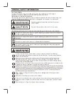
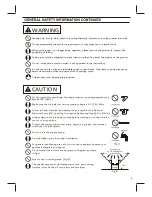
Warning Concerning Removal of Covers. The unit should be serviced by qualified technicians only. 
Your product is designed and manufactured to ensure a minimum of maintenance. Should your unit 
require service or parts, call Panasonic Call Center at 1-866-292-7299 (USA) or 1-800-669-5165 (Canada).
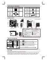
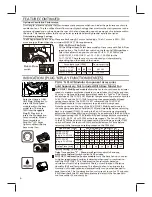
SPECIFICATIONS

Specifications  for  Base  Model  fans

Fig.20

lnsulation

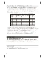
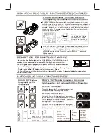
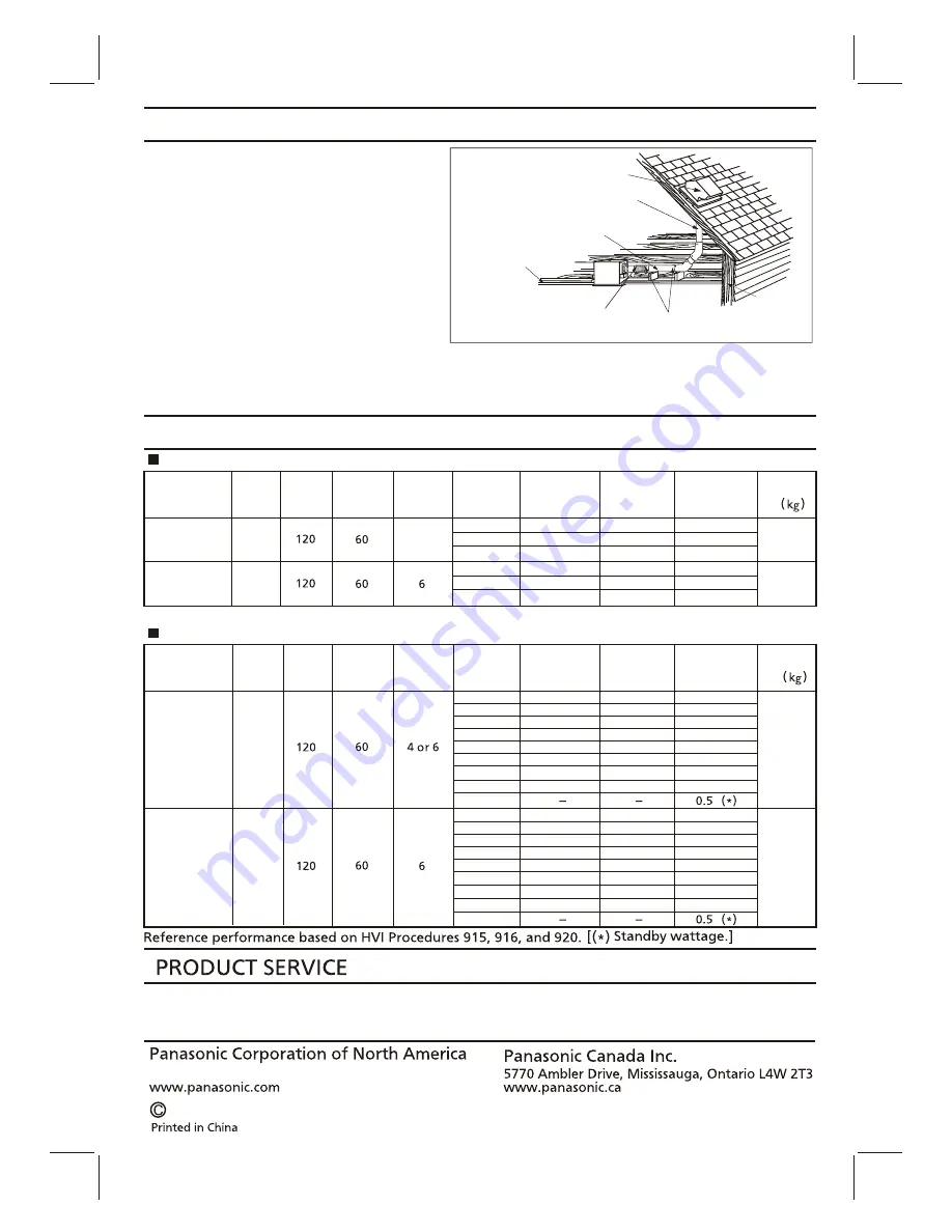
PRACTICAL GUIDE TO INSTALLATION

4 inches or 6 inches roof jack, wall cap,
or soffit vent with backdraft damper

Mechanically connect duct to termination
and seal with mastic or approved foil
faced tape

2-3 ft straight run before elbow
ln attic installation,
caulk box to drywall

Short piece of flexible duct helps
alignment and absorbs sound.
Clamps plus mastic or approved
foil faced tape at all flex joints

Foil tape tightly covers all metal
duct joints (glue PVC joints)

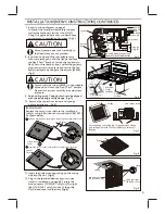
Properly  insulate  the  area  around  the  fan  to
minimize  building  heat  loss  and  gain.  (Fig.20)
Loose  fill  or  batt  insulation  can  be  placed
directly  over  the  fan  housing  in  the  attic.
Our  fans  and  fan/light  combination  units  do
not  create  excessive  heat  that  is  a  common
problem  with  recessed  light  fixtures  or  some
competitor’s  fan/light  combination.  Our
efficient,  cool-running  motors  and  our  LED
lighting  unit  do  not  create  enough  ambient
heat  to  be  subjected  to  these  limitations.

HVI Certified performance based on HVI Procedures 915, 916, and 920.

Specifications for Multi Speed fans

Model No.

Model No.

Air

direction

Air

direction

Exhaust

Exhaust

Exhaust

4 or 6

Exhaust

Voltage

(V)

Voltage

(V)

Frequency

(Hz)

Frequency

(Hz)

Noise

(sones)

Noise

(sones)

Speed

(rpm)

Speed

(rpm)

Power


(W)

Power


(W)

 Weight

Ib

.

 Weight

Ib

.

Duct

diameter

(inches)

Duct

diameter

(inches)

Air volume

at 0.1"WG

(CFM)

Air volume

at 0.1"WG

(CFM)

FV-05-11VKS1
FV-05-11VK1

FV-11-15VK1

FV-05-11VKS1,

FV-05-11VK1
(Plug-in 
FV-VS15VK1)

110

<0.3
<0.3

<0.3

<0.3

<0.3

<0.3

<0.3

<0.3
<0.3

<0.3

<0.3

<0.3

<0.3

<0.3

7.0

8.0

3.5

4.3

10.0

6.5

5.5
9.5

3.6

13.0

5.5

3.5
2.7
2.4

620

870

630

835

660

795

740

760

795

745

730

915

740

725

110

80

60

40

0

130

150

50
80

90

70

50

30

100

10.6(4.8)

10.6(4.8)

FV-11-15VK1
(Plug-in 
FV-VS15VK1)

<0.3

<0.3

<0.3

<0.3

<0.3

<0.3

<0.3

<0.3

7.4

4.9

7.0

4.4

5.6

3.8
3.6
3.1

625
620
615
610
605

595

600

590

100

80

60

0

110

90

70

50

120

10.6(4.8)

10.6(4.8)

The  ducting  from  this  fan  to  the  outside  of 
the  building  has  a  strong  effect  on  the  air  flow,  noise  and  energy  use  of  the  fan.Use  the  shortest, 
straightest  duct  routing  possible  for  best  performance,  and  avoid  installing  the  fan  with  smaller 
ducts  than  recommended.  Insulation  around  the  ducts  can  reduce  energy  loss  and  inhibit  mold 
growth.  Fans  installed  with  existing  ducts  may  not  achieve  their  rated  air  flow.

Summary of Contents for FV-05-11VKS1

Page 1: ...PLIED ACCESSORIES DIMENSIONS WIRING DIAGRAM FEATURE INDICATION PLUG N PLAY FUNCTION DEVICES DESCRIPTION FOR NIGHT LIGHT MODULE MOTION PLUG N PLAY FUNCTION DEVICES INSTALLATION PLUG N PLAY FUNCTION DEV...

Page 2: ...d shower enclosures For Your Safety To reduce the risk of injury loss of life electric shock fire malfunction and damage to equipment or property always observe the following safety precautions Explan...

Page 3: ...r dedicated parts such as mounting fixtures must be used if such parts are provided Do not install the unit where ducts are configured as shown in Fig A Adaptor CAUTION Canada only Not to be installed...

Page 4: ...100 105 110 Two Bedrooms Three Bedrooms Four Bedrooms Five Bedrooms DESCRIPTION These products are listed by UL under UL file No E78414 These products use a sirocco fan driven by a DC motor powered b...

Page 5: ...30 2 4 1 3 5 7 8 TM Flex Z Fast bracket with 4 tapping screws ST4 2X20 1 Multi Speed module FV 05 11VKS1 only other models not included Plug N Play module slot Plug N Play module slot Power switch Fan...

Page 6: ...efore returning to the lower speed setting chosen on the CFM dial Pick A Flow CFM Multi Speed Air volume CFM 50 110 110 130 150 0 0 0 0 0 0 40 40 40 60 60 60 40 60 60 80 80 80 40 70 80 100 100 100 40...

Page 7: ...FF 20 minutes time delay FV MSVK1 only Fan active At low speed When motion or excess humidity is detected fan runs at high speed Remains running at high speed until the delay time has passed FV CSVK1...

Page 8: ...ody by removing the machine screw M4X6 before installation Fig 1 IMPORTANT Remove the tape from damper and adaptor before installation As shown below The fan position between joists from 16 to 24 on c...

Page 9: ...age 5 Follow all the local electrical safety codes as well as the National Electrical Code NEC Using UL approved wire nuts connect house power wires to ventilating fan wires Fig 5 INSTALLATION NEW CON...

Page 10: ...e step 1 4 5 on page 8 and step 7 on page 9 Before connect the circular duct to the adaptor should pull down the circular duct from the ceiling Disconnect power source before working on unit 5 Follow...

Page 11: ...FV MSVK1 or FV NLVK1 Pull down the mounting spring that without lead wire passed side and remove motion sensor or LED night light as shown in Fig 16 Squeeze mounting spring and pull down carefully Dis...

Page 12: ...mbination Our efficient cool running motors and our LED lighting unit do not create enough ambient heat to be subjected to these limitations HVI Certified performance based on HVI Procedures 915 916 a...

Reviews: