
CAUTION
CAUTION
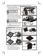
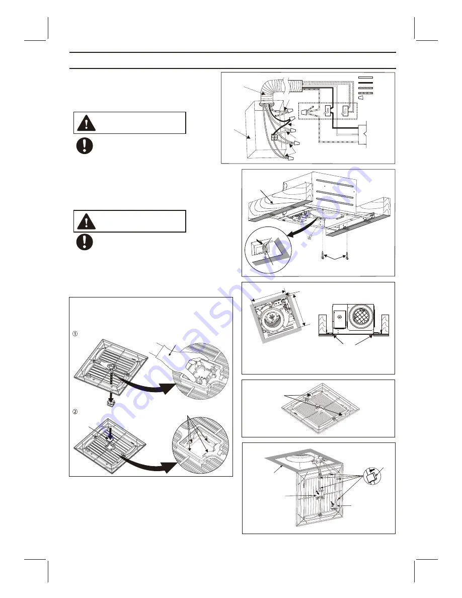
11.
Insert the grille mounting spring on the wiring
side into the slot.
(Fig.9)
12.
Plug in the specified devices as your choice
(refer to installation on page 8). Insert the
motion sensor (FV-MSVK1 only) or LED night
light (FV-NLVK1 only) into slot of the grille.
Fix the lead wire into the clasp
(Fig.9).
9
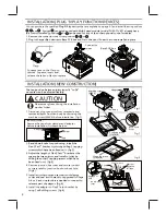
8. Insert fan body and slide into adapter assy
with some strength, untill the flange overlaps
TM
the Flex-Z Fast
bracket. Secure the fan body to
TM
Flex-Z Fast
bracket by using 2 self-drilling screws,
plug connector to receptacle and secure the fan
body to adaptor by using machine screw (M4X6).
(Fig.6)
Mount junction box cover carefully so
that lead wires are not pinched.
Secure machine screw (M4X6) to the suitable
TM
hole and not touch the Flex-Z Fast bracket.
Please fix the screw carefully to avoid screw
slip teeth.
10. Remove the tapes from louver and springs
before installation. (Fig.8)
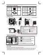
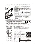
7. Refer to wiring diagram on page 5.
Follow all the local electrical safety codes as
well as the National Electrical Code (NEC).
Using UL approved wire nuts, connect house
power wires to ventilating fan wires. (Fig.5)
INSTALLATION (NEW CONSTRUCTION) CONTINUED
9. Finish ceiling work. Ceiling hole should be aligned
with the inside edge of the flange. (Fig.7)
Tapes
10 1/2
(270)
10 1/2
(270)
Fig.7
Fig.9
Fig.8
Unit: inches (mm)
After finishing the ceiling job, fill gap between flange
and ceillng with caulk or other sealant to prevent air
leakage
Ceiling
Fig.6
Machine
screw
(M4X6)
2 Self-drilling
screws
Joist
Plug connector
Receptacle
Motion sensor
(FV-MSVK1 only)
LED night light
(FV-NLVK1 only)
Clasp
Ceiling
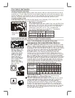
IMPORTANT:
Replace the sensor cover before the installation
(only for plug-in Motion sensor modular FV-MSVK1).
As shown below:
Keep on pressing the clasps when removing the ornamental cover.
Sensor
cover
Insert the sensor cover (attachment for FV-MSVK1) into slot.
Gloves
Ornamental
cover
Fig.5
120 VAC
LINE IN
Switch box
Junction
box
L
N
Conduit
Earth ground
Earth ground
Live
Netural
Two red wires (Connect to a
general manual wall switch)
BLACK
WHITE
RED
GREEN
Wire nuts


