background image

3

Do  not  install  this  ventilating  fan  where  interior  room  temperature  may 
exceed  104°F(40°C).

Make  sure  that  the  electric  service  supply  voltage  is  AC  120V,  60Hz.

Follow  all  local  electrical  and  safety  codes,  as  well  as  the  National 
Electrical  Code  (NEC)  and  the  Occupation  Safety  and  Health  Act  (OSHA).

Always  disconnect  the  power  source  before  working  on  or  near  the  fan, 
motor,  light  fixture  or  junction  box. 

Protect  the  supply  wiring  from  sharp  edges,  oil,  grease,  hot  surfaces,
chemicals  or  other  objects.

Do  not  kink  the  supply  wiring.

Provide  make  up  air  for  proper  ventilation.

For  general  ventilating  use  only.  Do  not  use  to  exhaust  hazardous  or 
explosive  materials  and  vapors.

Not  for  use  in  cooking  area.  (Fig.B)

The  special-purpose  or  dedicated  parts,  such  as  mounting
fixtures,  must  be  used  if  such  parts  are  provided.

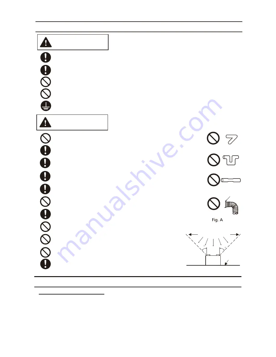
Do  not  install  the  unit  where  ducts  are  configured  as  shown 
in  Fig.A.

CAUTION

Ceiling  joist  must  be  subjected  to  static  load  more  than  five  times  the  weight  of  the  product.

Do  not  install  with  a  method  which  is  not  approved  in  the  instructions.

WARNING

This  product  must  be  properly  grounded.

Do  not  use  this  fan  with  any  solid-state  speed  control  device.  Solid  state  controls  may  cause
harmonic  distortion  which  can  cause  motor  humming  noise.

When  this  product  is  no  longer  being  operated,  please  remove  the  product  to  prevent  the 
possibility  of  falling.

GENERAL SAFETY INFORMATION


CONTINUED

Prohibited

Prohibited

Prohibited

Prohibited

Floor

45

45

Cooking

equipment

(Cooking area)

Do not install above or

inside this area

Adaptor

Fig. B

Spot and Continuous Ventilation:

   These fans are designed to run continuously ensuring a healthy

environment at low CFM levels 24 hours a day. By utilizing the optional CustomVent Multi-Speed module
the fans are built to run continuously at a pre-set lower level (FV-05-11VKSL1 and FV-05-11VKL1: 0, 30, 
40, 50, 60, 70, 80, 90, 100 CFM; FV-11-15VKL1: 0, 50, 60, 70, 80, 90, 100, 110, 120 CFM). The setting is 
dependent on the size of the house and the individual wishes of the homeowner. It is crucial that the


installer pre-set the lower setting during the installation. Please refer to the chart below and the 
switch indication on page 6. 

PLEASE READ PRIOR TO INSTALLING THIS FAN

Summary of Contents for FV-05-11VKSL1

Page 1: ...1 15VKL1 INSTALLATION INSTRUCTIONS Ventilating Fan Model No Contents FV 05 11VKSL1 FV 05 11VKL1 FV 11 15VKL1 Representative models 2 3 3 4 4 4 5 5 5 6 6 7 7 8 8 10 10 11 11 BACK COVER BACK COVER BACK...

Page 2: ...ibe the level of hazard injury and property damage caused when the denotation is disregarded and improper use is performed To reduce the risk of fire electric shock or injury to persons observe the fo...

Page 3: ...th a method which is not approved in the instructions WARNING This product must be properly grounded Do not use this fan with any solid state speed control device Solid state controls may cause harmon...

Page 4: ...gral transformer The motor is designed to have long operating life high dynamic response higher speed ranges with saving energy The grille covering the fan body is a spring loaded quick remove type A...

Page 5: ...ight Neutral Power supply AC120V 60Hz AC120V 60Hz Power supply Neutral Black Red Red Green Earth ground Green White White 114 C Fuse Thermally protected Hi Low switch When plug in Multi Speed module s...

Page 6: ...the high speed setting Selecting a particular TIME option will cause the fan to run for the selected amount of time before returning to the lower speed setting chosen on the CFM dial Pick A Flow CFM...

Page 7: ...ecessary to connect wall switch when only plug in FV NLVK1 fan can operate on high speed with wall switch control fan can also operate on low speed when used in combination with the FV VS15VK1 INDICAT...

Page 8: ...or from fan body by removing the machine screw M4X6 before installation Fig 1 IMPORTANT Remove the tape from damper and adaptor before installation As shown below The fan position between joists from...

Page 9: ...black Light Netural to white Netural to white Junction box Two red wires Connect to a general manual wall switch Earth ground to green INSTALLATION NEW CONSTRUCTION CONTINUED CAUTION CAUTION Machine s...

Page 10: ...fan body to adaptor by using machine screw M4X6 Fig 16 Secure machine screw M4X6 to the suitable TM hole and not touch the Flex Z Fast bracket Please fix the screw carefully to avoid screw slip teeth...

Page 11: ...t immerse motor in water when cleaning Do not soak resin parts in water over 140 F 60 C WARNING CAUTION 4 Install the LED lamps CX GU24 H B 7W as shown in step 1 and step 2 of Fig 9 Page 9 WARNING Rem...

Page 12: ...rection Exhaust Exhaust Exhaust 4 or 6 Exhaust Voltage V Voltage V Frequency Hz Frequency Hz Noise sones Noise sones Speed rpm Speed rpm Power W Power W Fan Fan Lighting unit Lighting unit Weight lb W...

Reviews: