


4
PLEASE READ PRIOR TO INSTALLING THIS FAN CONTINUED
These fans are also built to take care of the homeowner’s spot ventilation needs when the room is
occupied. The basic fan models allow a choice of three speeds. When fans are equipped with the optional
Multi-Speed module, these models kick up to a maximum level of 150 CFM for the FV-11-15VKL1 and 110
CFM for the FV-05-11VKSL1 and FV-05-11VKL1 either when the switch is turned on or activated by the
optional Condensation Sensor module or the optional Motion Sensor module.
A High/Low Delay Timer, located inside the fan unit, is utilized to return the fan back to the pre-set
Continuous ventilation mode. The installer needs to consult with the homeowner for the desired
setting on the timer (0 - 60 minutes) and make the adjustments during the installation.
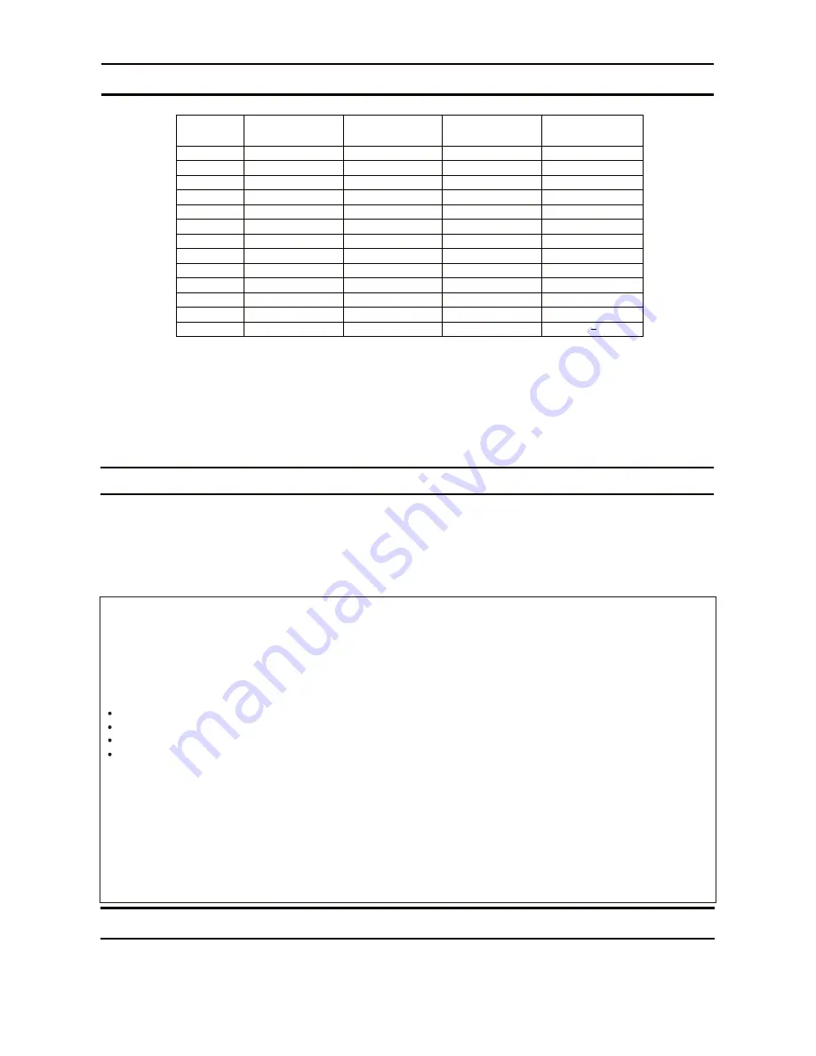
CustomVent Multi-Speed module (Lower Setting). ASHRAE 62.2-2010
(sq.feet)
<1,000
1,500
2,000
2,500
3,000
3,500
4,000
4,500
5,000
5,500
6,000
6,500
7,000
33
38
43
48
53
58
63
68
73
78
83
88
93
40
45
50
55
60
65
70
75
80
85
90
95
100
48
53
58
63
68
73
78
83
88
93
98
103
108
55
60
65
70
75
80
85
90
95
100
105
110
Two Bedrooms Three Bedrooms Four Bedrooms
Five Bedrooms
DoC Responsible Party:
Panasonic Corporation of North America
Two Riverfront Plaza, Newark, NJ 07102
1-866-292-7299
Customer Call Support:
Risk of Fire: Type IC-Inherently Protected, Only Use LED Lamp, Max 7W, Type GU24.
This device complies with Part 15 of the FCC Rules. Operation is subject to the following two conditions:
(1) This device may not cause harmful interference, and (2) this device must accept any interference
received, including interference that may cause undesired operation.
DESCRIPTION
These products are listed by UL under UL file No. E78414.
These products use a sirocco fan driven by a DC motor powered by an integral transformer. The motor is
designed to have long operating life, high dynamic response, higher speed ranges with saving energy.
The grille covering the fan body is a spring-loaded, quick remove type. A damper for preventing air counter
flow is provided. The blower uses a high-capacity sirocco fan developed to reduce the noise level.
FCC Note: This equipment has been tested and found to comply with the limits for a Class B digital device,
pursuant to Part 15 of the FCC Rules. These limits are designed to provide reasonable protection against
harmful interference in a residential installation. This equipment generates, uses and can radiate radio
frequency energy and, if not installed and used in accordance with the instructions, may cause harmful
interference to radio communications. However, there is no guarantee that interference will not occur in
a particular installation. If this equipment does cause harmful interference to radio or television reception,
which can be determined by turning this product on and off, the user is encouraged to try to correct the
interference by one of the following measures:
The lighting unit is an energy-saving LED lighting device that uses two 7W LED lamps and produces almost
the same illumination as a standard 60W incandescent lamp.
Reorient or relocate the receiving antenna.
Increase the separation between the equipment and receiver.
Connect equipment into outlet on a circuit different from that to which the receiver is connected.
Consult the dealer or an experienced radio/TV technician for help.
Warning: This equipment must be installed by qualified person in accordance with the provided installation
instructions; and all applicable codes and standards. Also, any changes or modifications not expressly
approved by the party responsible for compliance could void the user’s authority to operate this equipment.
UNPACKING
Unpack and carefully remove the unit from carton.
Refer to the Supplied Accessories list to verify that all parts are present.


