


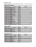
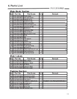
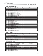

FV-0811RQL1
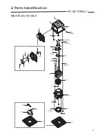
4. Parts List
14
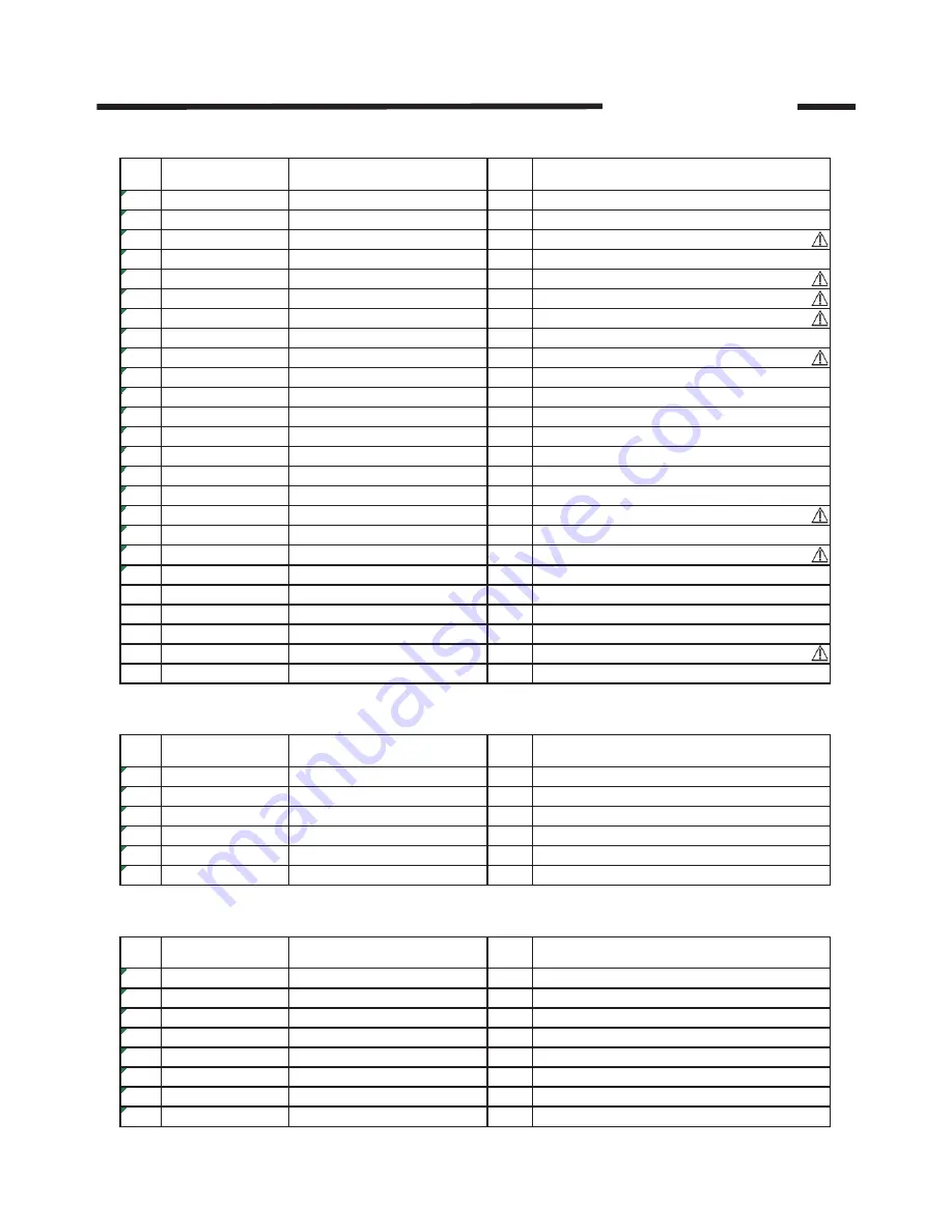
No.
Part No.
Part Name
Q'ty
Remark
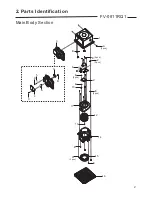
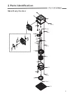
1
FFV1600138S Frame Assy
1
2
FFV0800001S Casing Support
3
3
FFV0000181S Adapter Assy
1
4
FFV2800012S Junction Cover
1
5
FFV3450010S Earth Lead Wire
1
6
FFV0900069S Connector Assy (L)
1
7
FFV0900059S Connector Assembly(V)
1
8
FFV0900074S Connector Plate
1
9
FFV3702320S Motor Unit
1
10
FFV0760062S Condenser Box
1
11
FFV0740027S Nylon Clamp
1
12
FFV3730137S Motor Support Unit
1
13
FFV0400103S Blade
1
14
FFV7020021S Nut
1
15
FFV0790126S Casing Unit
1
16
FFV4300160S Orifice
1
17
FFV3400160S Louver Section
1
18
FFV3400161S Louver Unit
1
19
FFV3400148S Led Unit
1
20
FFV2520040S Insulation Plate
1
A
FFV7000065S Bind Screw
6
B
FFV7000108S Truss Tap Screw
2
C
FFV7000064S Bind Screw
1
D
FFV7000203S Earth Lead Wire Screw
1
E
FFV7000089S Truss Tap Screw
15
No.
Part No.
Part Name
Q'ty
Remark
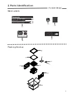
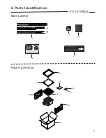
21
FFV4020939S Name Plate
1
22
FFV0810011S Caution Label 1
1
23
FFV2260003S UL Mark
1
24
FFV0810010S Caution Label
1
25
FFV6730109S FCC Label
1
26
FFV6730045S Warning Label
1
No.
Part No.
Part Name
Q'ty
Remark
27
FFV2230024S Hanger Assembly
1
28
FFV4710381S Louver Case Assy
1
29
FFV4650016S Poly Cover
1
30
FFV2540220S Installation Instructions
1
English,For CA Market/USA Market
31
FFV0010238S Accessory A
1
32
FFV4710382S Left Pad
1
33
FFV4710383S Right Pad
1
34
FFV9001383S Packing Case
1
Main Body Section
Main Labels
Packing Section
Summary of Contents for FV-0811RQ1
Page 2: ...1 Specifications 1 ...
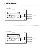
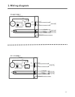
Page 11: ...3 Wiring diagram 10 3 Wiring diagram ...
Page 12: ...3 Wiring diagram 11 ...


