
1
InstructIon Manual
Digital Fiber Sensor
FX-100-Z
Series
MEUEN-FX100Z V1.0
Thank you for purchasing products from Panasonic Electric Works SUNX
Co., Ltd. Please read this Instruction Manual carefully and thoroughly for
the correct and optimum use of this product. Kindly keep this manual in a
convenient place for quick reference.
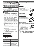
WARNING
●
Never use this product as a sensing device for personnel protection.
●
In case of using sensing devices for personnel protection, use prod-
ucts which meet laws and standards, such as OSHA, ANSI or IEC
etc., for personnel protection applicable in each region or country.
1
cautIons
●
This product has been developed / produced for industrial use only.
●
Make sure that the power supply is off while wiring.
●
If a voltage exceeding the rated range is applied, or if an AC power
supply is directly connected, the product may get burnt or damaged.
●
Short-circuiting the load or incorrect wiring may burn or damage the
product.
●
Do not run the wires together with high-voltage lines or power lines
or put them in the same raceway. This can cause malfunction due to
induction.
●
Verify that the supply voltage variation is within the rating.
●
If power is supplied from a commercial switching regulator, ensure that
the frame ground (F.G.) terminal of the power supply is connected to
an actual ground.
●
If noise generating equipment (switching regulator, inverter motor, etc.)
is used in the vicinity of this product, connect the frame ground (F.G.)
terminal of the equipment to an actual ground.
●
Do not use during the initial transient time (0.5s) after the power sup-
ply is switched on.
●
You can extend the cable up to 100m max. with 0.3mm
2
or more
cable. However, in order to reduce noise, make the wiring as short as
possible.
●
Make sure that stress is not applied to the sensor cable joint, e.g. by
forcible bending or pulling.
● Take care that the product is not directly exposed to fluorescent lamp
from a rapid-starter lamp, a high frequency lighting device or sunlight,
etc. as it may affect the sensing performance.
●
This product is suitable for indoor use only.
●
Avoid dust, dirt, and steam.
●
Take care that the product does not come in contact with oil, grease,
organic solvents, such as thinner, etc., strong acid or alkalines.
● This product cannot be used in an environment containing inflam
-
mable or explosive gases.
●
Never disassemble or modify the product.
●
EEPROM is adopted to this product. Teaching is limited to 100,000
times because of the EEPROM's lifetime.
2
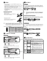
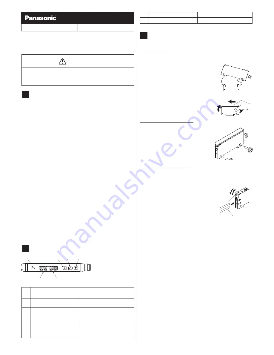
Part DEscrIPtIon
1
6
5
4
3
2
no.
Part
Description
1
Output indicator (orange)
Lit when output is active.
2
Mode key
●
Select mode
● Confirm settings
3
ON key / Set value UP key
●
Select settings in teaching mode
●
Increase set value
●
Select various other settings
4
OFF key / Set value DOWN key
●
Select settings in teaching mode
●
Decrease set value
●
Select various other settings
5
Green digital display
Threshold value
no.
Part
Description
6
Red digital display
Incident light intensity
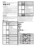
3
MountInG
When using a DIn rail
*
You may break the spring hook if you do not follow the mounting
instructions carefully.
How to mount the amplifier
1.
Fit the spring hook on a 35mm DIN rail and
push forward.
2.
Slip the front part of the mounting section
over the DIN rail and release.
1
2
35mm
How to remove the amplifier
1.
Push the amplifier forward.
2.
Lift up the front part of the amplifier.
1
2
When using screws with washers
Use M3 screws with washers to mount the
amplifier.
Do not use a tightening torque of more than 0.5
N•m or you may break the housing.
M3 screw
with washers
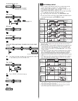
How to connect the fiber cable
Be sure to fit the attachment to the fibers first before inserting the fibers into
the amplifier. For details, refer to the Instruction Manual enclosed with the
fibers.
1.
Snap the fiber lock lever down until it
stops completely.
2.
Slowly insert the fiber cables into the
inlets until they stop (see note).
If the fiber cables are not inserted until
they stop, the sensing range reduces.
Since a flexible fiber is easily bent, be
careful when inserting it.
3.
Return the fiber lock lever to the original
position.
1
3
2
Fiber lock
lever
Fiber
*
If the cable is a coaxial reflective type fiber, e.g. FD-G4 or FD-
FM2, insert the single-core fiber cable into the beam-emitting
inlet “P” and the multi-core fiber cable into the beam-receiving
inlet “D.” If they are inserted in reverse, the sensing perfor
-
mance will deteriorate.


