
2
4
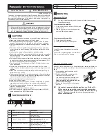
WIrInG
●
Use the cable with the connector
CN-24A-C
q
(optional)
when con-
necting this product.
● Tighten the fixing ring of the cable with connector completely by hand
when mounting. The tightening torque: 0.3 to 0.4N
•
m.
●
Make sure to hold the side surface of this product when tightening or
loosening the fixing ring of the cable with connector.
● If the fixing ring is tightened by a tool such as pliers, the connector
may be damaged.
● If the tightening torque is not enough, the fixing ring may loosen due to
vibration, etc.
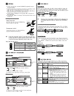
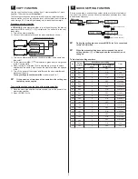
Attaching the connector cable
connection method
Insert the cable with connector
CN-24A-C
q
as
shown. Tighten the fixing ring.
Fixing ring
Cable with
connector
CN-24A-C
□
Disconnection method
Loosen the fixing ring, and, holding the fixing
ring, pull to separate the connector.
Fixing ring
*
Before disconnecting the cable, loosen the fixing ring com
-
pletely. If the cable is pulled by excessive force (15N or more)
when the fixing ring is tightened, the cable may break.
connector pin arrangement
1
2
4
3
connector pin no.
terminal name
1
+V
2
External input
3
0V
4
Output
5
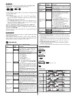
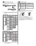
I/o cIrcuIt DIaGraMs
NPN output type
+
–
8V
*
±10%
Main circuit
Internal circuit
Users’ circuit
100mA max.
(Brown) +V
(Black) Output
(Blue) 0V
(White) External input
Color code of cable with connector
Load
Connector pin No.
12 to 24V DC
* Non-voltage contact or NPN open-collector transistor
or
●
High (+8V to +V DC or Open): Invalid
●
Low [(0 to +2V DC (source current 0.5mA or less)]: Valid
PNP output type
*
+
–
±10%
Main circuit
Internal circuit
Users’ circuit
100mA max.
(Brown) +V
(Black) Output
(Blue) 0V
(White) External input
Color code of cable with connector
12 to 24V DC
Load
Connector pin No.
* Non-voltage contact or PNP open-collector transistor
or
●
High [+4V to +V DC (Sink current 0.5 to 3mA or less)]: Valid
●
Low (0 to +0.6V DC or Open): Invalid
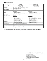
6
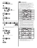
run MoDE
Digital display
When you turn ON the power, the product name is indicated in green and
the emission frequency is indicated in red. Then the device automatically
switches into RUN mode, in which the threshold value is displayed in green
and the incident light intensity in red.
Power ON
Emission
frequency
Product
name
RUN mode
Incident light
intensity
Threshold
value
Automatic
*
What appears on the display is effected by the settings for the
external input and ECO mode. For details, see PRO MODE on
page 4.
Threshold value fine adjustment function
Change the threshold value in RUN mode by pressing <UP> or <DOWN>.
Hold down the key to make the value change faster. The threshold value is
stored after 3s.
RUN mode
Incident light
intensity
Threshold
value
Key lock function
The key lock function prevents settings from being changed inadvertently.
is displayed if you press a key when the key lock function is set.
Press <MODE> + <DOWN> for at least 2s to set or release the key lock
function.
Set key lock
RUN mode
Press for 2 sec.
Automatic
Release key lock
RUN mode
Press for 2 seconds
Automatic
Automatic
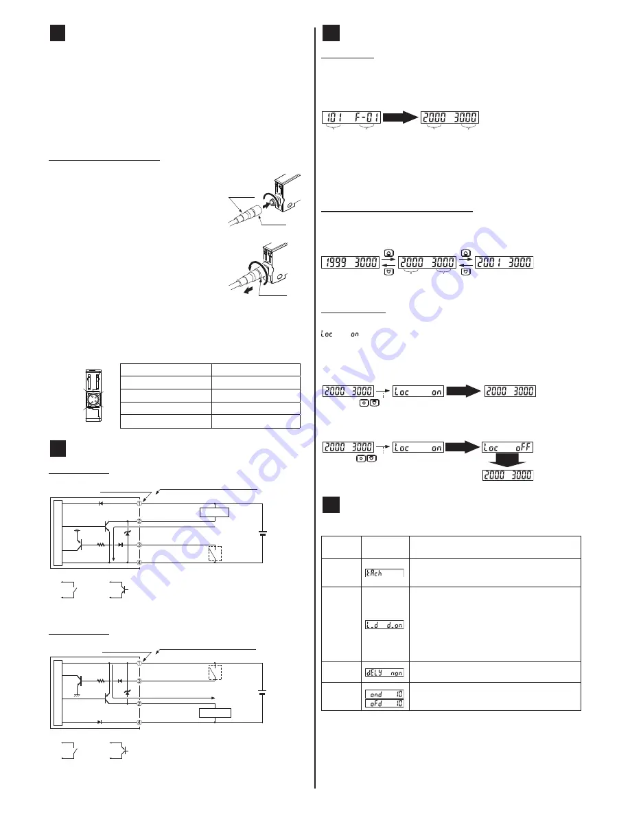
7
sEttInG MoDE
To enter SETTING mode, press <MODE> for 2s in RUN mode. While in
SETTING mode, press <MODE> briefly to move from one selection to the
Item
Factory set
-
ting
Description
Teaching
A threshold value can be set in 2-point teaching, limit
teaching or full-auto teaching.
For details, see
tEacHInG MoDE
on page 7.
Output
operation
Light-ON or Dark-ON can be set.
●
light-on
means the output will turn ON when
the incident light intensity is in the brighter of
the two 2 sensing states (object present/object
absent).
●
Dark-ON
means the output will turn ON when
the incident light intensity is in the darker of
the two 2 sensing states (object present/object
absent).
Timer
selection
Three settings are possible: no timer, ON delay timer,
or OFF delay timer.
Timer
delay
You can specify the delay for the ON delay timer or
OFF delay timer.
If no timer is set, this mode is not displayed.


