
3
Item
Factory set
-
ting
Description
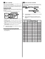
Emission
level
If the incident light intensity is saturated, which makes
sensing impossible or unreliable, you can reduce the
emission level.
●
Level 3 (
): Normal
●
Level 2 (
): Approx. 40% of normal
●
Level 1 (
): Approx. 20% of normal
When you select Auto ( ), proper light intensity is
automatically set only during limit teaching.
*
For differences between the conventional and
modified units, see
unIt VErsIons
on page
7.
Emission
frequency
FX-102
□
-Z
FX-101
□
-Z
When using fiber heads in parallel, interference can be
prevented by setting different emission frequencies.
When emission frequency 0 is set, interference cannot
be prevented. Response time corresponds to emission
frequency. For details, see
sPEcIFIcatIons
on
page 8.
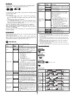
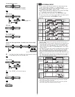
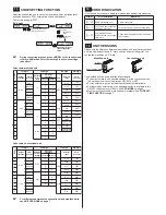
Flowchart for sEttInG mode
run mode
Press for 2s.
sEttInG mode
Automatic
teaching
output operation
Light-ON
Dark-ON
timer operation
1, 5, 10, 20, 40, 50, 100, 500, 1000ms
:
Without timer
Timer delay
Timer delay
Timer delays setting mode
Timer delays setting mode
ON delay timer
OFF delay timer
Timer delays available (ms):
Emission level
Level 2
Level 3
Auto + Level 3
Level 1
Emission frequency
FX-101
□
-Z
FX-102
□
-Z
FX-101
□
-Z
FX-102
□
-Z
Emission
frequency 0
Emission
frequency 1
Emission frequencies available:
Emission frequencies available:
*
The operation indicator and the beam-emitting inlet blink while the
emission frequency is being set. When the emission frequency is
set to 0, they light up. The blinking cycle depends on each emission
frequency (emission frequency 1: fast ↔ emission frequency 4:
slow).
run mode
8
tEacHInG MoDE
*
Beware that detection may become unstable if too little margin
between the theshold value and incident light intensity is al
-
lowed for the environment when teaching.
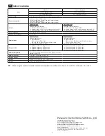
2-point teaching
2-point teaching is the most common teaching method and means the
threshold value is taught using two points that correspond to the object
present and object absent conditions.
Light-ON or Dark-ON is determined automatically for the output operation
setting.
Output indicator ON when object is present
In teaching mode, press <ON> when object is present to set
the first incident light intensity.
Thru-beam type
Light interrupted
condition
Light received condition
Mark
Reflective type
Base
Automatic
The first incident light intensity is set and is displayed in
green. The red LED display blinks and is ready to be set to
the object absent condition.
To cancel, press <MODE>.
Remove the object and press <OFF> to complete 2-point
teaching.
Thru-beam type
Light received condition
Light interrupted condition
Mark
Reflective type
Base
Automatic
The margin between the first and second incident is displayed
in red (P=%). When the margin is 200% or more,
is
displayed.
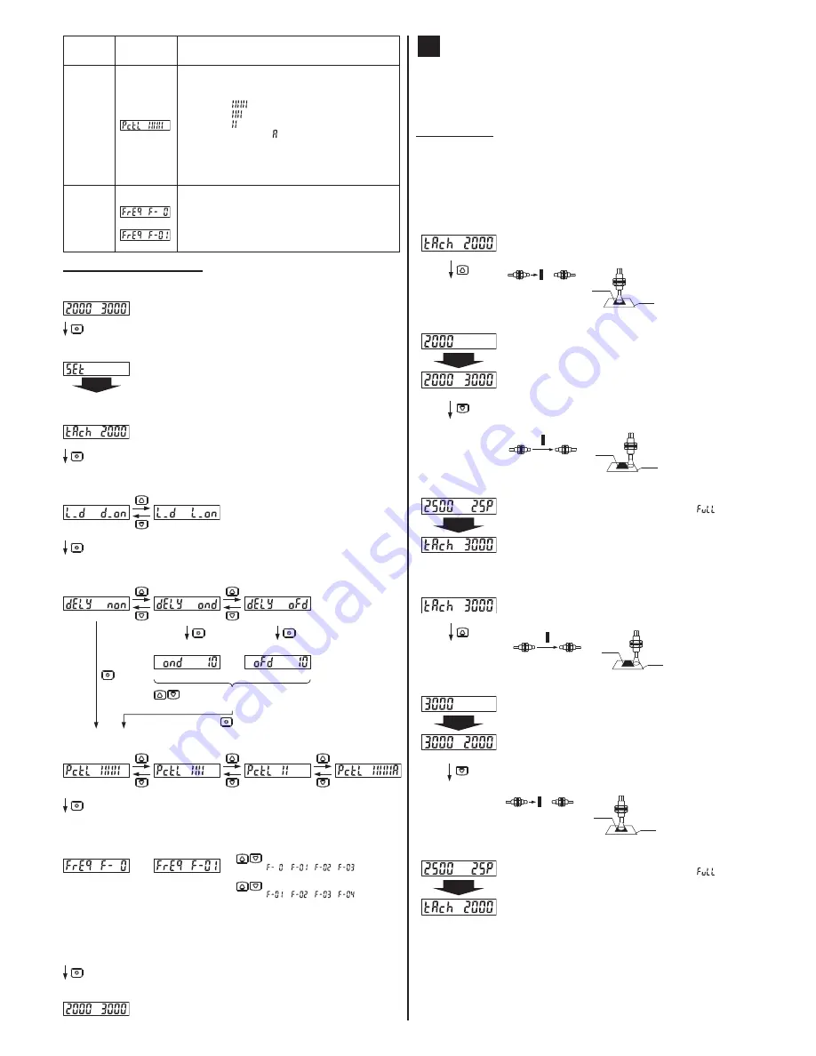
Output indicator ON when object is absent
In teaching mode, press <ON> when object is absent to set
the first incident light intensity.
Thru-beam type
Light received condition
Light interrupted condition
Mark
Reflective type
Base
Automatic
The first incident light intensity is set and is displayed in
green. The red LED display blinks and is ready to be set to
the object present condition.
To cancel, press <MODE>.
Place the object so that it is sensed and press <OFF> to
complete 2-point teaching.
Thru-beam type
Light interrupted
condition
Light received condition
Mark
Reflective type
Base
Automatic
The margin between the first and second incident is displayed
in red (P=%). When the margin is 200% or more,
is
displayed.


