INSTRUCTION MANUAL
Digital Fiber Sensor
FX-100-Z
series
MJE-FX100ZC No.0035-67V
Thank you very much for purchasing Panasonic products. Read this Instruction Manual
carefully and thoroughly for the correct and optimum use of this product. Kindly keep
this manual in a convenient place for quick reference.
WARNING
● Never use this product as a sensing device for personnel protection.
● In case of using sensing devices for personnel protection, use products which
meet laws and standards, such as OSHA, ANSI or IEC etc., for personnel protec-
tion applicable in each region or country.
1
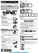
PART DESCRIPTION
Digital display (Green)
(Threshold value)
Digital display (Red)
(Incident light intensity)
MODE key
• Selection of setting items
• Confirmation of set contents
ON key / Set value UP key
• Selection of setting contents
• Settings in teaching mode
OFF key / Set value DOWN key
• Selection of setting contents
• Settings in teaching mode
Operation indicator
(Orange)
2
MOUNTING
<When using a DIN rail>
How to mount the amplifier
1.
Fit the rear part of the mounting section of the amplifier
on DIN rail.
2.
Press down the rear part of the mounting section of the
unit on the
DIN rail and fit the front part of the mounting
section to the DIN rail.
35mm width DIN rail
1
2
How to remove the amplifier
1.
Push the amplifier forward.
2.
Lift up the front part of the amplifier to remove it.
Note: Take care that if the front part is lifted without pushing the amplifier forward,
the hook on the rear portion of the mounting section is likely to break.
1
2
<When using screws with washers>
● Use M3 screws with washers for mounting. The tighten-
ing torque should be 0.5N·m or less.
M3 screw with
washer
How to connect the fiber cable
Be sure to fit the attachment to the fibers first before inserting the fibers to the ampli-
fier. For details, refer to the Instruction Manual enclosed with the fibers.
1.
In cover open condition, snap the fiber lock lever down,
till it stops completely.
2.
Insert the fiber cables slowly into the inlets until they
stop. (Note 1)
3.
Return the fiber lock lever to the original position, till it
stops.
Fiber
Fiber lock lever
1
3
2
Notes: 1) In case the fiber cables are not inserted to a position where they stop, the sensing range reduces. Since a
flexible fiber is easily bent, take care when it is inserted.
2) With the coaxial reflective type fiber, such as,
FD-42G
or
FD-61G
, insert the single-core fiber cable into the
beam-emitting inlet “
P
” and the multi-core fiber cable into the beam-receiving inlet “
D
.” If they are inserted in
reverse, the sensing performance will deteriorate.
3
WIRING
● Make sure to use the cable with connector
CN-24A-C
□ (optional) when connecting
to this product.
● Tighten the fixing ring of the cable with connector completely by hand when mount-
ing. (The tightening torque: 0.3 to 0.4N·m)
● Make sure to hold the side surface of this product when tightening or loosening the
fixing ring of the cable with connector.
● If the fixing ring is tightened by a tool such as pliers, it may cause connector damage.
● If the tightening torque is not enough, the fixing ring may loosen due to vibration, etc.
Connection method
● Insert the cable with connector
CN-24A-C
□ (optional)
into this product’s connector area as shown in the right
figure.
Cable with
connector
CN-24A-C
□
Disconnection method
● Loosen the fixing ring, and, holding the fixing ring, pull
to separate the connector.
Note: Before disconnecting, make sure to check that the fixing ring is completely
loosened. If the cable is pulled by excessive force (15N or more) when the
fixing ring is tightened, the cable may break.
Fixing ring
<Connector pin arrangement>
1
2
3
4
Connector pin No.
Terminal name
1
+V
2
External input
3
0V
4
Output
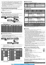
4
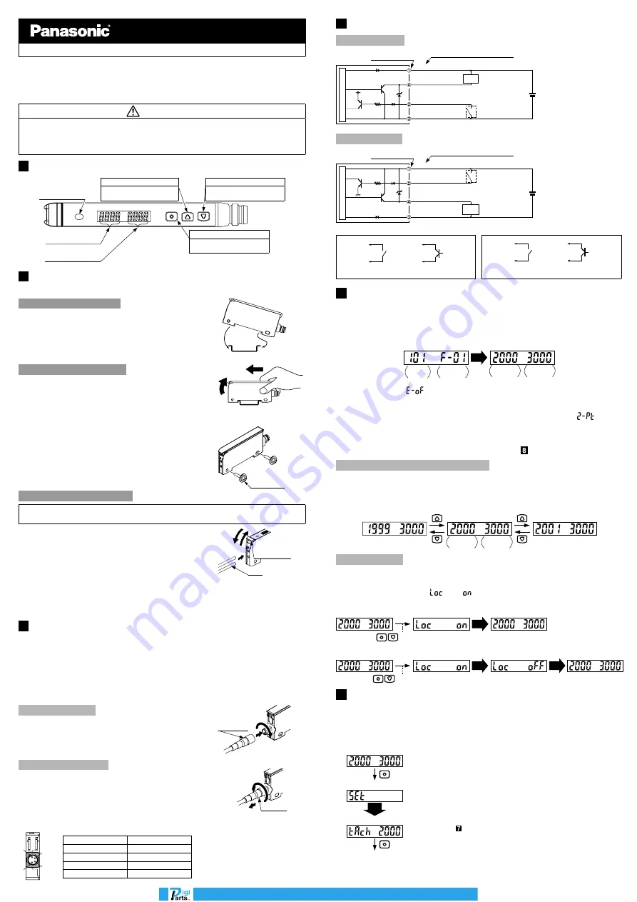
I/O CIRCUIT DIAGRAMS
NPN output type
+
12 to 24V DC
±10%
-
Main circuit
(Black) Output
(White) External input
(Blue) 0V
Load
8V
Connector pin No.
(Brown) +V
Color code of cable with connector
*1
PNP output type
Load
*2
+
12 to 24V DC
±10%
-
(Black) Output
(White) External input
(Blue) 0V
Connector pin No.
(Brown) +V
Color code of cable with connector
Main circuit
*1
*2
Non-voltage contact or NPN open-collector transistor
or
High (+8V to +V DC or Open): Invalid
Low [(0 to +2V DC (Source current 0.5mA or less)] : Valid
Non-voltage contact or PNP open-collector transistor
or
High [+4V to +V DC (Sink current 0.5 to 3mA or less)]: Valid
Low (0 to +0.6V DC or Open): Invalid
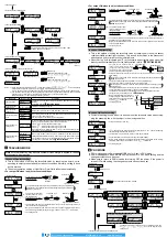
5
RUN MODE
<Digital display>
● When turning ON the power, the product name is indicated on the green digital dis-
play, while the emission frequency is indicated on the red digital display. Then switch-
es into RUN mode [digital display (green: threshold value, red: incident light intensity)].
AUTO
<When turning ON the power>
Emission
frequency
<RUN mode>
Product
name
Threshold
value
Incident light
intensity
● When selecting emission halt in the external input setting mode and receiving the
signal externally, “
” is indicated on the red digital display.
● When selecting ECO in the external input setting mode, key operation on the main
body is invalid during external input.
● When selecting 2-point teaching in the external input setting mode, “
” is indi-
cated on the green digital display after inputting the first point.
● When ECO setting mode is ON, the digital display turns off in approx. 20 sec. In
case of lighting up the digital display again, press any key for 2 sec. or more.
● For the settings of external input and ECO, refer to “
PRO MODE
.”
Threshold value fine adjustment function
● Fine adjustment of threshold value can be done when in RUN mode.
● Press the set value UP key or set value DOWN key to change threshold value.
(Hold down the key to make the value change faster.)
● The threshold value is stored after 3 sec.
Threshold
value
Incident light
intensity
When in RUN mode
Keylock function
● The keylock function prevents key operations so that the conditions set in each setting
mode are not inadvertently changed.
● In the keylock condition, “
” is displayed when pressing any key.
<Keylock set>
<When in RUN mode>
Press for 2 sec.
AUTO
<Keylock released>
Press for 2 sec. or more
<When in RUN mode>
AUTO
AUTO
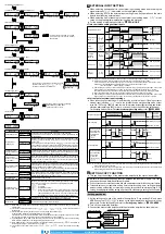
6
SETTING MODE
● Setting mode appears after
pressing MODE key for 2 sec. in RUN mode.
● RUN mode appears when MODE key is pressed for 2 sec. while setting and the
changed contents have been set.
● Make sure to return to RUN mode before turning OFF the power. If the power is
turned OFF while setting, the changed contents have not been set.
<Setting mode>
Press for 2 sec.
Press for 2 sec.
<Teaching mode>
<Output operation setting mode>
For details, refer to “
TEACHING MODE
.”
AUTO
info@digiparts.ch
www.digiparts.ch
Ihr Schweizer Industriepartner


