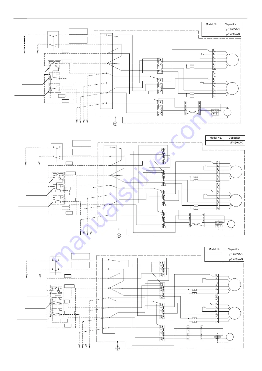
background image

Second main body

Power Source
(Line)

Power Source
(Neutral)

SW1

Common

Switch

Damper

High

SW2

High

Main unit

L

N

SW1

SW2

Common

Low

Damper

Terminal

board

White

Black

Brown

Blue

Grey

White

White

Blue

Black

Black

Red

Red

Black

Grey

Grey

Brown

Blue

Relay  4

Black

Red

Red

Black

White

Black

White

White

Yellow

Yellow

Relay  1

Black

Grey

Black

Relay  2

Relay  3

White

White
Yellow

Grey

Black

Black

(Connector)

Capacitor

White

White

White(Extra high)

Blue(High)

Yellow

Red

Orange

Orange

Connector

Red

Yellow

Blue

Supply

Air Fan

(Connector)

Connector

White

White(Extra high)

White

Black

Black

Capacitor

Yellow

Red

Blue(High)

Orange

Orange
Red

Yellow

Blue

Exhaust

Air Fan

Yellow

Yellow

White

White

Black

Black

Blue

Connector

Connector

Micro switch

Damper

Motor

Blue

650ZDY8

6.0

Power Source

220-240V~single

phase 50Hz

Blue

Black

Grey

Grey

Brown

Relay  4

Black

Red

Red

Black

White

Black

Black

White

White

Yellow

Yellow

Relay  1

Grey

Black

Relay  2

Relay  3

White

White
Yellow

Grey

Black

Black

(Connector)

Capacitor

White

White

White(Extra high)

Blue(High)

Yellow

Red

Orange

Orange

Connector

Red

Yellow

Blue

Supply

Air Fan

(Connector)

Connector

White

White(Extra high)

White

Black

Black

Capacitor

Yellow

Red

Blue(High)

Orange

Orange
Red

Yellow

Blue

Exhaust

Air Fan

Yellow

Yellow

White

White

Black

Black

Blue

Blue

Connector

Connector

Micro switch

Damper

Motor

Power Source
(Line)

Power Source
(Neutral)

SW1

Common

Switch

Damper

High

SW2

High

Main unit

L

N

SW1

SW2

Common

Low

Damper

Terminal

board

Grey

White

White

Blue

Black

Black

Red

Red

White

Black

Brown

Blue

Second main body

800ZDY8

01KZDY8A

10.0

10.0

Power Source

220-240V~single

phase 50Hz

Power Source

220-240V~single

phase 50Hz

Power Source
(Line)

Power Source
(Neutral)

SW1

Common

Switch

Damper

High

SW2

Second main body

High

Main unit

L

N

SW1

SW2

Common

Low

Damper

Terminal

board

Grey

White

White

Blue

Black

Black

Red

Red

White

Black

Brown

Blue

Black

Red

Red

Black

White

Brown

Black

Black

Black

White

White

Yellow

Yellow

Relay  1

Relay  2

Relay  3

White

White
Yellow

Grey

Black

Black

(Connector)

Capacitor

White

White

White(Extra high)

Blue(High)

Yellow

Red

Orange

Orange

Connector

Red

Yellow

Blue

Supply

Air Fan

(Connector)

Connector

White

White(Extra high)

White

Black

Black

Capacitor

Yellow

Red

Blue(High)

Orange

Orange
Red

Yellow

Blue

Exhaust

Air Fan

Yellow

Yellow

White

White

Black

Black

Blue

Connector

Connector

Micro switch

Damper

Motor

350ZDY8

500ZDY8

3.5

6.0

Low

PL

Low

Low

PL

PL

Function Select Switch
(3) Energy Recovery

Ventilation

(1) Normal Ventilation

Air Flow Switch

(3) High
(1) Low

Operation Switch

0 (OFF)
1 (ON)

Function Select Switch
(3) Energy Recovery

Ventilation

(1) Normal Ventilation

Air Flow Switch

(3) High
(1) Low

Operation Switch

0 (OFF)
1 (ON)

Function Select Switch
(3) Energy Recovery

Ventilation

(1) Normal Ventilation

Air Flow Switch

(3) High
(1) Low

Operation Switch

0 (OFF)
1 (ON)

14

Electric works

12

Summary of Contents for FY-01KZDY8A

Page 1: ...gy Systems Guangdong Co Ltd Service Manual This Service Manual is written for the after sail service department especially for the fix and maintenance workers Energy Recovery Ventilator sold in Europe market Model No ...

Page 2: ...r and Heat Exchange Element maintenance and periodic spot checks of the unit can be easily carried out Refer to the Model Installation for its space Do not install the unit in locations such as machinery or chemical plants where it will be exposed to noxious gases containing acids alkali organic solvents paint fumes etc to gases containing corrosive ingredients or where dust or oil mist will be pr...

Page 3: ...16 4 ...

Page 4: ...60 45 5 5 2 5 2 2 0 1 3 5 0 3 0 3 3 5 2 3 5 5 2 5 2 2 0 1 3 5 0 3 0 3 3 5 2 3 B d e s i o N Temperature Exchange Efficiency 75 75 78 Dimensions mm Weight kg Model No Item Power Source Ventilation Mode w o L h g i H h g i h a r t x E w o L h g i H h g i h a r t x E h c t o N 5 8 1 5 6 1 5 2 2 4 0 2 9 8 2 3 6 2 5 8 1 5 6 1 5 2 2 4 0 2 9 8 2 3 6 2 W t u p n I 0 4 4 0 0 5 0 0 5 0 4 4 0 0 5 0 0 5 h m e...

Page 5: ...Specifications 7 ...

Page 6: ...Performance P Q curve FY 250ZDY8 FY 350ZDY8 FY 500ZDY8 FY 650ZDY8 FY 800ZDY8 FY 01KZDY8A 8 ...

Page 7: ...65 8 65 A 20 600 A EA RA SA OA EA RA SA OA 600 A Model FY 350ZDY8 and FY 500ZDY8 have two Heat Exchange Element kg kg 370 10 Cautions for Operation 9 ...

Page 8: ... 4 13 30 Oval hole F G 4 3 B J N E 5 6 2 2 2 2 1 H H I A E 8 8 9 10 G G F 11 7 4 3 C C B J P N L M K 8 Model No FY 350ZDY8 and FY 500ZDY8 have two Heat Exchange Element Model No FY 350ZDY8 and FY 500ZDY8 have different fan and motor locations Model No FY 01KZDY8A has four Heat Exchange Elements Model No FY 650ZDY8 has different fan and motor locations Note2 Note1 Note2 Note1 414 1050 70 978 112 58...

Page 9: ...ads from High to Extra high Power Source 220 240V single phase 50Hz Yellow Yellow White White Black Black Blue Connector Connector Connector Connector White White Extra high White Black Black Black Black Connector Capacitor Capacitor White White Yellow Red Blue High Orange Orange Red Yellow Blue White Extra high Blue High Yellow Red Orange Orange Connector Red Yellow Blue Supply Air Fan Exhaust Ai...

Page 10: ...switch Damper Motor Power Source Line Power Source Neutral SW1 Common Switch Damper High SW2 High Main unit L N SW1 SW2 Common Low Damper Terminal board Grey White White Blue Black Black Red Red White Black Brown Blue Second main body 800ZDY8 01KZDY8A 10 0 10 0 Power Source 220 240V single phase 50Hz Power Source 220 240V single phase 50Hz Power Source Line Power Source Neutral SW1 Common Switch D...

Reviews: