background image

Specific Caution Items

Checking Location of Installation

This Energy Recovery Ventilators have been designed especially for use in offices, conference rooms, etc.
Please check to ensure that neither the main unit nor the inlet-outlet grill are installed in any of the following locations.

When Using

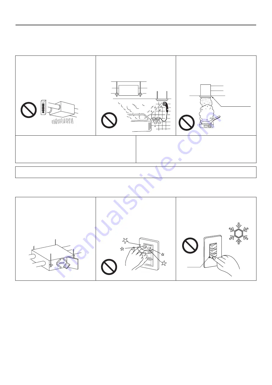
Locations exposed to high temperatures or
direct flame.

Avoid installing the Energy Recovery Ventilators
or the inlet-outlet grill in locations which reach 
temperatures of 40°C or above.
Usage under high temperature conditions may 
cause distortion of the filter or Heat Exchange 
Element or motor burn-out.

Locations with high humidity.

Do not install in high humidity locations such as
bathrooms.
Doing so may cause a breakdown of the unit or 
an electric shock.

Locations with large amounts of oily 
smoke, such as food preparation areas.

The unit will become inoperable if the filter or 
Heat Exchange Element become clogged with
oil.

Make sure that Inspection Opening is provided so that filter and
Heat Exchange Element maintenance and periodic spot checks 
of the unit can be easily carried out. (Refer to the Model 
Installation for its space)

Do not install the unit in locations such as machinery or chemical
plants where it will be exposed to noxious gases containing
acids, alkali, organic solvents, paint fumes, etc., to gases 
containing corrosive ingredients, or where dust or oil mist will be
produced.

If there are any problems concerning the location or installation of the unit, please consult either store from which it was purchased
or the agent who installed it.

Always be sure to use a filter.
Failure to do so may cause dust and dirt to
build up on the heat exchange element, 
lowering its efficiency and rendering it 
inoperable.

Operate the switch with certainty.
In particular, suddenly turning the switch 
on and off will not only cause improper
operation of the unit, but will also affect the
relay inside the switch, and may damage 
it.

40°C

Interior Intake Vent

Oily

smoke

Never operate the on “Normal ventilation” 
during the winter when the room is being 
heated, as this will cause condensation to 
form inside the unit and in the inlet-outlet 
vent.

Normal
ventilation

ENGLISH

5

3

Summary of Contents for FY-01KZDY8A

Page 1: ...gy Systems Guangdong Co Ltd Service Manual This Service Manual is written for the after sail service department especially for the fix and maintenance workers Energy Recovery Ventilator sold in Europe market Model No ...

Page 2: ...r and Heat Exchange Element maintenance and periodic spot checks of the unit can be easily carried out Refer to the Model Installation for its space Do not install the unit in locations such as machinery or chemical plants where it will be exposed to noxious gases containing acids alkali organic solvents paint fumes etc to gases containing corrosive ingredients or where dust or oil mist will be pr...

Page 3: ...16 4 ...

Page 4: ...60 45 5 5 2 5 2 2 0 1 3 5 0 3 0 3 3 5 2 3 5 5 2 5 2 2 0 1 3 5 0 3 0 3 3 5 2 3 B d e s i o N Temperature Exchange Efficiency 75 75 78 Dimensions mm Weight kg Model No Item Power Source Ventilation Mode w o L h g i H h g i h a r t x E w o L h g i H h g i h a r t x E h c t o N 5 8 1 5 6 1 5 2 2 4 0 2 9 8 2 3 6 2 5 8 1 5 6 1 5 2 2 4 0 2 9 8 2 3 6 2 W t u p n I 0 4 4 0 0 5 0 0 5 0 4 4 0 0 5 0 0 5 h m e...

Page 5: ...Specifications 7 ...

Page 6: ...Performance P Q curve FY 250ZDY8 FY 350ZDY8 FY 500ZDY8 FY 650ZDY8 FY 800ZDY8 FY 01KZDY8A 8 ...

Page 7: ...65 8 65 A 20 600 A EA RA SA OA EA RA SA OA 600 A Model FY 350ZDY8 and FY 500ZDY8 have two Heat Exchange Element kg kg 370 10 Cautions for Operation 9 ...

Page 8: ... 4 13 30 Oval hole F G 4 3 B J N E 5 6 2 2 2 2 1 H H I A E 8 8 9 10 G G F 11 7 4 3 C C B J P N L M K 8 Model No FY 350ZDY8 and FY 500ZDY8 have two Heat Exchange Element Model No FY 350ZDY8 and FY 500ZDY8 have different fan and motor locations Model No FY 01KZDY8A has four Heat Exchange Elements Model No FY 650ZDY8 has different fan and motor locations Note2 Note1 Note2 Note1 414 1050 70 978 112 58...

Page 9: ...ads from High to Extra high Power Source 220 240V single phase 50Hz Yellow Yellow White White Black Black Blue Connector Connector Connector Connector White White Extra high White Black Black Black Black Connector Capacitor Capacitor White White Yellow Red Blue High Orange Orange Red Yellow Blue White Extra high Blue High Yellow Red Orange Orange Connector Red Yellow Blue Supply Air Fan Exhaust Ai...

Page 10: ...switch Damper Motor Power Source Line Power Source Neutral SW1 Common Switch Damper High SW2 High Main unit L N SW1 SW2 Common Low Damper Terminal board Grey White White Blue Black Black Red Red White Black Brown Blue Second main body 800ZDY8 01KZDY8A 10 0 10 0 Power Source 220 240V single phase 50Hz Power Source 220 240V single phase 50Hz Power Source Line Power Source Neutral SW1 Common Switch D...

Reviews: