background image

Summary of Contents for FZ-10

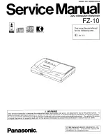
Page 1: ...blic It does not contain warnings or cautions to advise non technical individuals of potential dangers in attempting to service a product Products powered by electricity should be serviced or repaired only by experi_enced professional technicians Any attempt to service or repair the product or products dealt with in this service information by anyone else could result in serious injury or death Pa...

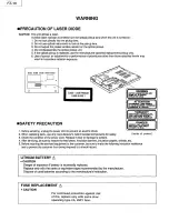
Page 2: ... LABER IIMUllE EH CM O OU IERT IE EXPOSmON DANClEAEIJSE All FAISCEAU VORSICHT UNSICHTIWlE I ASERSllWUJNO WElft BEOmET IIClf1 OEM STRAK AUSSETZEH DANGER IIMSIII LASER RADIATION WIEH OPEii AYOIO DIRECT EXPOSlflE TO BEAM 2 When replacing parts use only manufacturer s recommended components for safety Onside of prcxlucl 3 Check the condition of the power cord Replace if wear or damage is evident 4 Aft...

Page 3: ...new plug is to be fitted please observe the wiring code as shown below If in any doubt please consult a qualified electrician Important The wires in this mains lead are coloured in accordance with the following code Blue Neutral Brown Live As the colours of the wires in the mains lead of this appliance may not correspond with the coloured markings identifying the terminals in your plug proceed as ...

Page 4: ...recautions for Traverse Deck 2 1 2 2 Disassembly Reassembly 2 2 2 3 Troubleshooting Table 2 5 2 4 Terminal Function of IC s 2 6 3 Diagrams and Replacement Parts List 3 1 Wiring Connection diagram 3 1 3 2 Schematic Diagrams 3 2 3 3 Printed Circuit Boards 3 1 O 3 4 Service Notes and Precaution 3 13 3 5 Service Tools 3 14 3 6 Exploded Views and Replacement Parts List 3 15 3 7 Electrical Replacement P...

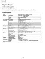
Page 5: ...lors Max 16 7 Million Std 32K Audio Stereo 16 bit PCM Samplina 44 1 kHz Storage CD ROM drive Size 12 and 8 cm CD single Double Soeed CD ROM Drive Read Buffer 32 KB Extension memory via Expansion Port 1 0 Port Control port Low speed 1 0 Dsub 9 pin x 1 Daisv chain svstem Expansion port Hiah speed 1 0 30 pin x 1 AV Expansion port Hiah speed AV I O Video CD Adaptor 68 pin x 1 System System dimensions ...

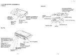
Page 6: ...ately sold FMV cartridges Lights up when CD is being accessed Expansion Port EXPANSION Slot for peripheral devices which utilize high speed data transfer Power switch POWER When using a television which supports S video connecting a separately sold S video cable results in a sharper picture Right Left audio output socket AUDIO OUT R L Video output socket VIDEO OUT 1 2 Controller Connector Connecte...

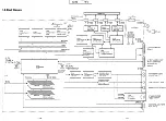
Page 7: ... i _ 5V 9V Data f I f Slow BUS I I I IC600 IC660 DA623851 PVJ MN1882410FZA CD ROM Interface 1 chip Microprocessor CNsoo Gate Array __ X151 f 50 0MHz I SYSTEM CLOCK X153 IC120 59 0MHz MN7B003ABK T ANVIL VIDEO CLOCK CN500 1 L IC200 IC220 Q260 Q261 Q262 32 DA431 0VME2XQ I DANJM2902MTP Q263 Q500 Q501 32 Audio DAC Audio Amp I Mute Circuit Address Serial Data O1ao orn1 O1a4 I Data I I Video Amp I I 2M b...

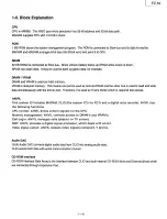
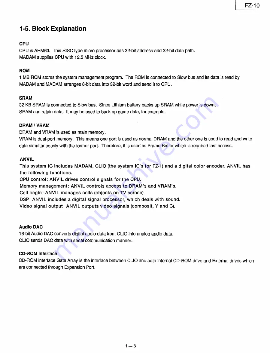
Page 8: ...te data simultaneously with the former port Therefore it is used as Frame Buffer which is required fast access ANVIL This system IC includes MADAM CLIO the system IC s for FZ 1 and a digital color encoder ANVIL has the following functions CPU control ANVIL drives control signals for the CPU Memory management ANVIL controls access to DRAM s and VRAM s Cell engin ANVIL manages cells objects on TV sc...

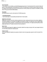
Page 9: ...n system Digital Servo Processor Digital Servo Processor have some functions as optical servo focus tracking and traverse servo process digital pro cess EFM modulation error correction and digital servo process for S Motor The optical servo will not require adjust ment for its gain offset and balance manually because it does all automatically The Digital processing block provides digital signal ba...

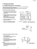
Page 10: ...g the short pin finish the job in as short time as possible 3 Take care not to apply excessive stress to the flexible board FPC board 4 Do not turn the variable resistor laser power adjustment It has already been adjusted I Traverse Deck Variable resistor Be sure to short this portion Do not touch Use the shorting pin or clip Wrist strap Anti static bracelet Grounding for electrostatic breakdown p...

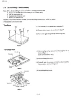
Page 11: ...in any part of the system Reassemble in the reverse order Top Case Figure 1 Traverse Unit Pin B Pin B Figure 2 Insulator Figure 3 1 Turn this unit FZ 10 upside down and place it 2 Remove seven screws A as shown in figure 1 3 Turn it over again and gradually raise the top case 1 After removing the top case remove the two pins B as shown in figure 2 Push from the bottom side 2 Remove the traverse co...

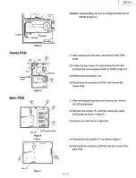
Page 12: ...and remove the AC inlet terminal and remove power switch as shown in figure 5 3 Remove the two screws D 4 Disconnect the connector CN101 and remove the Power PCB 1 After removing the top case and traverse unit remove the LED guide panel 2 Remove five screws E and then remove the upper shield plate as shown in figure 6 3 Remove the FMV cover at right side 4 Remove the two screws F as shown in figur...

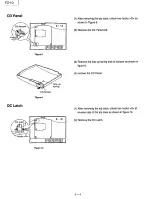
Page 13: ...op case unlock two hooks G as shown in Figure 8 2 Remove the CD Panel unit 3 Remove the hop up spring and oil dumper as shown in figure 9 4 remove the CD Panel 1 After removing the top case unlock two hooks H at reverse side of the top case as shown in figure 10 2 Remove the DC Latch 2 4 ...

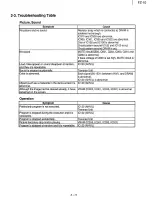
Page 14: ...n playina Prooram is stoooed at random and it is repeatable 2 5 FZ 10 Cause Resistor array which is connected to DRAM is solder_ed not enough IC31 0 and IC330 are abnormal IC300 IC301 IC320 and IC322 are abnormal One of IC120 and IC1 00 is abnormal Circuit pattern around IC120 and IC1 00 is cut Circuit pattern around DRAM is cut MUTE circuit O500 0501 0263 0262 0261 and 0260 is abnormal If base vo...

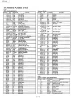
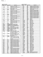
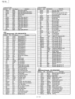
Page 15: ...t A12 Address 12 50 Out A11 Address 13 51 Vdd Power supply 52 Vss Ground 53 Out A10 Address 10 54 Out A9 Address 9 55 Out A8 Address 8 56 Out A7 Address 7 57 Out AG Address 6 58 Out A5 Address 5 59 Out A4 Address 4 Continued IC100 Pin No l O Pin Name Comment 60 Out A3 Address 3 61 Out A2 Address 2 62 Out A1 Address 1 63 Out AO Address 0 64 Vss Ground 65 Vdd Power suoolv 66 lnout TTL ABE Address Bu...

Page 16: ... LRAS2 Row address strobe for left DRAM data bits 31 161 VRAM data bits 31 161 69 0 RRAS3 Row address strobe for right DRAM data bits 15 01 70 GND Ground 34 0 LRAS1 Row address strobe for left VRAM data bits 31 161 35 VDD Power supply 36 I XV251N Video clock input from the on board clock network 37 0 XV25OUT Video clock output to the on board clock network 38 GND Ground 39 I X251N System clock inp...

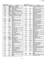
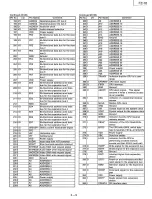
Page 17: ...D7 Data bus 7 106 0 PDCS2 Slow bus chip select signal 1 160 GND Ground 107 0 PDCS3 Slow bus chip select signal 2 161 1 0 D8 Data bus 8 108 0 SRAMW SRAM write enable 162 1 0 D9 Data bus 9 109 GND Ground 163 1 0 D10 Data bus 10 110 0 SRAMR SRAM output enable 164 1 0 D11 Data bus 11 111 0 PDWR Slow bus read enable When 165 VDD Power supply accessing the ROM ANVIL uses 166 1 0 D12 Data bus 12 this sig...

Page 18: ... bus for the expansion bus 3 access 212 GND Ground 265 0 MCLK Master CPU clock 213 1 0 ED4 Bi directional address annd data 266 GND Ground bus for the expansion bus 4 267 I XIN Crystal input for the system clock 214 1 0 ED5 Bi directional address annd data 268 0 XOUT Crystal output for the system clock bus for the expansion bus 5 269 GND Ground 215 1 0 ED6 Bi directional address annd data 270 I MR...

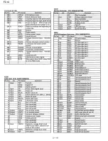
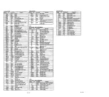
Page 19: ...MEO ROM output enable 0 18 Out ROME1 ROM output enable 1 19 Out ROMCS ROM chip selection 20 Input CPURES CPU reset IC200 21 1 0 EDO Internal expansion bus 0 Audio DAC P N DA4310VME2XQ 22 1 0 ED1 Internal expansion bus 1 Pin No 1 0 Pin Name Comment 23 GND Ground 1 Input TST1 Test pin 24 l 0 ED2 Internal expansion bus 2 2 DVDD Digital 5V 25 l 0 ED3 Internal expansion bus 3 3 DVSS Digital ground 26 1...

Page 20: ...nout CS Chio selection from Microprocessor 78 Out CDHRD CD drive read 54 lnout RS Reaister selection 79 Out CDHWR CD drive write 55 VDD Power suoolv 80 Out CDCMD CD command 56 vss Ground 57 1 0 DO Microprocessor data 0 IC640 58 l O D1 Microprocessor data 1 Error Correction P N DA98000KV26V 59 1 0 D2 Microprocessor data 2 Pin No l O Pin Name Comment 60 1 0 D3 Microprocessor data 3 1 Out RA9 Data bu...

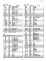
Page 21: ...71 VREF Reference voltaQe for ADC 11 Out CA3 ROM Address 3 72 AVDD Analoa oower supply 12 Out CA2 ROM Address 2 73 VDD Power suoolv 13 Out CA1 ROM Address 1 74 D7 External data bus 7 14 Out CAO ROM Address 0 75 D6 External data bus 6 15 Input EX External bus selection 76 D5 External data bus 5 16 lnout RST Reset 77 D4 External data bus 4 17 Out RE Read enable 78 D3 External data bus 3 18 Out WE Wr...

Page 22: ... LOON Laser ON 12 CEA Caoacitor nin for HPF Arnn 41 Out TES Trackinn error shunt 13 CSBOO Capacitor pin for detecting envelope of 42 Out PLAY Plav black nortion in RF 43 Out WVEL Status sinnal in double sneed mode 1 Out BOO BOO outout 44 lnout ARF RF innut 45 lnout IREF Reference current 15 CSBRT Capacitor pin for detecting envelope o blinh1 nonibnin RF 46 lnout ORF Biasterminal for DSL 16 Out OFT...

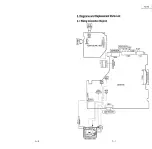
Page 23: ...PPLY PCB 0 IAUDIO OUT IVIQEO L R OUT RF OUT IEXPANSION I S VIDEO 3DL CN620 o t CN761 CN760 61 11 I 4 1 CN720 ON763 111 I 1 11ool T t I I I Z j I 0 I C I I Q SW721 I I I I r I I I ___ 0 ___J _____ l I 1 I Ii I I I l I 1 5 I J _I I I 6 9 I I t TRAVERSE UNIT CONTROLLER 3 1 MAIN PCB CN500 IC520 it z a 0 0 z z n 0 X w ...

Page 24: ...AS210 AfELB 4 S liltUO sm1 100 t RDTOEB 1 8 RDlOEID ACASB 2 T RCASeD RSOEOB 3 6 RSO D10 RIEUB 4 5 RIIEUID RJ i12 10014 RRA611B 1 B RRASDBD RSC 2 7 RS D RQSF 5 RQSFO RDU 4 6 HDSFO 17 m o s o s o s o s RAl20100J4 1 B _ __ RAUi 100 4 1 a 3i 8 4 _ 6 M322 I00 4 I 8 R 1 3 3 100 4 1 8 RAB24H14 1t lr B AA325 47x4 1 e AB28 H 4 1 8 Amr 4hc 1 8 s RJ 30010014 1 8 3 6 4 6 R 301 10014 I e Rl 302 1001t 1 B Al 80...

Page 25: ... DABAI03SSF1E Co Plllllf Lm COOT ELESH8R8JA 250nt11W 39 40 Rll2 Am FSAL t 1 _l 41 JV V_w 251 lflllkl IV 42 3 8 Cll 20 _ AJ 1 l 0 43 mo DTC114TU 14 7Y ii2iio omuu t 44 om IIA111 _ rd 01c1m 45 CNIO I _ l 46 J M IN PCB l101 POWER CB 47 i 1001 3 9 lfflSTB I I 48 LOOI n CHU AV UPANSIOII POIIT DI IQ OPTIQM AL M mmwv 49 rboo 11ITCH m I COO 11 I C l I L Jh _001 FZ 10 i I 50 ...

Page 26: ...3 3 Printed Circuit Boards 3 3 1 Main PCB 3 10 FZ 10 FZ 10 1 i I 3 11 ...

Page 27: ...ower section to prevent high voltage When servicing with playing aCD tape SW720 to be pressed as shown in figure below SW720 Tape Open Close SWltch Precaution for measuring waveform When you observe waveform at points 3 and 4 on the schematic diagram measure It from bottom side of the built up unit See figure below Bottom Cabin et nnooo on D D o O 0 4 CJ 0 0 0 0 3 0 0 0 VREF approx 2 5V l Control ...

Page 28: ...PPLY 1 FZ 10 CHECKER WITH MANUAL 1 CABLE FOR FZ 10 CHECKER Cable with the device that connects the cable with 1 FZ 10 TRAVERSE PLATFORM WITH MANUAL In order to check circuit under the traverse you can 1 place it on the platform FLAT CABLE 11 PIN 1 FLAT CABLE 6 PIN 1 FLAT CABLE 4 PIN 1 CABLE 1 CABLE 1 J1 MAIN PCB 111111111 I olB IB IB 00000000 0 I 0 3D0 IM OIAGN lSIS 111 Q I DDDDDDDDD I 111111111 I...

Page 29: ...__Fz 19_J 3 6 Exploded Views and Replacement Parts List Kl 4 K1 K7 K2 r K2 1 N1 K11 N1 3 15 K4 ...

Page 30: ... 1 DFHG337ZA FOOT 3 DFMD9038ZA COVER TRAVERSE 4 DFMC0342ZA SHIELD PLATE LOWER 5 DFMC0343ZA SHIELD PLATE UPPER 6 DFMX0364ZA SHIELD PLATE POWER SOURCE 7 DFHG413ZA INSULATOR 8 DFKE0299ZA 0 LID FMV CONNECTOR 9 DFGL0040ZA LIGHT LEADING PANEL 10 DFHR5330ZB PIN TRAVERS 11 DFUN0020ZA SPRING 12 DFBH3011ZA OIL DAMPER 13 DFGP0161ZA 0 PANEL CD 14 DFBM0002ZA LATCH DC 1 XTB3 16GFZ SCREW 2 DFHE5036ZA SCREW Acces...

Page 31: ...CTROLYTIC 6 3 V 470 µF 1 C 184 ECl A0GKA471 Q CAPACITOR ELECTROLYTIC 4 V 470 µF 1 C 185 ECUV1C104ZFV CAPACITOR CERAMIC CHIP 16 V 0 1 µF 1 C 200 ECUV1C104ZFV CAPACITOR CERAMIC CHIP 16 V 0 1 µF 1 C 201 ECA1CM101B CAPACITOR ELECTROLYTIC 16 V 100 µF 1 C 202 ECA1HM100B CAPACITOR ELECTROLYTIC 50 V 1 µF 1 C 203 ECA1CM101B CAPACITOR ELECTROLYTIC 16 V 100 µF 1 C 205 ECUV1C104ZFV CAPACITOR CERAMIC CHIP 16 V...

Page 32: ...ITOR CERAMIC CHIP 50 V 1000 pF 10 1 C 705 ECUV1C104ZFV CAPACITOR CERAMIC CHIP 16 V 0 1 µF 1 C 706 ECUV1 H123KBV CAPACITOR CERAMIC CHIP 50 V 12000 pF 10 1 C 707 DCUC1 E224KBY CAPACITOR CERAMIC CHIP 25 V 220000 pF 10 1 C 708 DCUC1 C334KBY CAPACITOR CERAMIC CHIP 16 V 330000 pF 10 1 C 709 710 ECUV1C104ZFV CAPACITOR CERAMIC CHIP 16 V 0 1 µF 2 C 720 ECA1HM220B CAPACITOR ELECTROLYTIC 50 V 22 µF 1 C 721 E...

Page 33: ...224KBY CAPACITOR CERAMIC CHIP 25 V 22000 pF 10 1 C 794 ECUV1 H561 KBV CAPACITOR CERAMIC CHIP 50 V 560 pF 5 1 C 800 ECUV1C104ZFV CAPACITOR CERAMIC CHIP 16 V 0 1 µF 1 C 900 ECUV1H102KBV CAPACITOR CERAMIC CHIP 50 V 1000 pF 10 1 C 901 902 ECUV1 H561 KBV CAPACITOR CERAMIC CHIP 50 V 560 pF 5 2 C 903 904 ECUV1H102KBV CAPACITOR CERAMIC CHIP 50 V 1000 pF 10 2 C 905 906 ECUV1H101 KCV CAPACITOR CERAMIC CHIP ...

Page 34: ... OP AMP 1 L 122 123 DDAZSR10KT Y FERRITE BEAD 2 L 150 151 DDB5Z021 D Y FERRITE BEAD 2 L 154 155 DDB5Z021 D Y FERRITE BEAD 2 L 170 ELESN3R3JA INDUCTOR 3 3uH 1 L 172 ELESN3R3JA INDUCTOR 3 3uH 1 L 174 ELESN3R3JA INDUCTOR 3 3uH 1 L 180 DDB5Z021 A Y FERRITE BEAD 1 L 420 DDB5Z021 E Y FERRITE BEAD 1 L 503 ERJ3GEY0R00V CHIP JUMPER 1 L 506 507 ERJ3GEY0R00V CHIP JUMPER 2 L 600 DDB5Z021 D Y FERRITE BEAD 1 L ...

Page 35: ...IP 1 16W 22 kQ 5 1 R 128 ERJ3GEYJ222V RESISTOR THICK FILM CHIP 1 16W 2 2 kQ 5 1 R 129 130 ERJ3GEYJ223V RESISTOR THICK FILM CHIP 1 16W 22 kQ 5 2 R 131 ERJ3GEYJ101V RESISTOR THICK FILM CHIP 1 16W 100 Q 5 i R 135 ERJ3GEYJ472V RESISTOR THICK FILM CHIP 1 16W 4 7 kQ 5 1 R 150 ERJ3GEYJ101 V RESISTOR THICK FILM CHIP 1 16W 100 Q 5 1 R 151 ERJ3GEYJ471V RESISTOR THICK FILM CHIP 1 16W 470 Q 5 1 R 153 ERJ3GEYJ...

Page 36: ...FILM CHIP 1 16W 47 kn 5 1 R 283 ERJ3GEYJ103V RESISTOR THICK FILM CHIP 1 16W 10 kO 5 1 R 284 ERJ6GEYJ221 V RESISTOR THICK FILM CHIP 1 10W 220 n 5 1 R 285 ERJ3GEYJ473V RESISTOR THICK FILM CHIP 1 16W 47 kn 5 1 R 340 ERJ3GEYJ222V RESISTOR THICK FILM CHIP 1 16W 2 2 kn 5 1 R 400 ERJ3GEYJ471V RESISTOR THICK FILM CHIP 1 16W 470 n 5 1 R 401 ERJ3GEYJ103V RESISTOR THICK FILM CHIP 1 16W 10 kn 5 1 R 402 ERJ3GE...

Page 37: ...LM CHIP 1 16W 10 kQ 5 1 R 750 ERJ3GEYJ473V RESISTOR THICK FILM CHIP 1 16W 47 kQ 5 1 R 751 ERJ3GEYJ103V RESISTOR THICK FILM CHIP 1 16W 10 kQ 5 1 R 752 ERJ3GEYJ473V RESISTOR THICK FILM CHIP 1 16W 47 kQ 5 1 R 753 ERJ3GEYJ123V RESISTOR THICK FILM CHIP 1 16W 12 kQ 5 1 R 760 ERJ3GEYJ t 53V RESISTOR THICK FILM CHIP 1 16W 15 kQ 5 1 R 761 ERJ3GEYJ332V RESISTOR THICK FILM CHIP 1 16W 3 3 kQ 5 1 R 762 ERJ3GEY...

Page 38: ...23 EXBV8V101JV RESISTOR ARAY 100 Q 4 RA 328 332 EXBV8V101JV RESISTOR ARAY 100 Q 5 RA 620 623 EXBV8V750JV RESISTOR ARAY 75 Q 4 RA 640 641 EXBV8V221JV RESISTOR ARAY 220 Q 2 RA 660 EXBV8V103JV RESISTOR ARAY 100 Q 1 RA 800 812 EXBV8V330JV RESISTOR ARAY 33 Q 3 SW 720 DFFA0004ZA SWITCH 1 X 151 DECL50000P2W OSCILLATOR 50 00MHz 1 X 153 DECL59000H1W OSCILLATOR 59 00MHz 1 X 640 EF0EN3385T4 CRYSTAL 33 8688MH...

Page 39: ...TJ561 T RESISTOR 1 2W 560 Q 5 1 R 007 ERG12SJW180E RESISTOR 1 4W 18 Q 5 1 R 008 ER0S2TKF4701 RESISTOR 1 4W 4 7K Q 5 1 R 009 ERG2SJW180E RESISTOR 2W 18 n 5 1 R 010 ERDS1TJ104T RESISTOR 1 2W 100K n 5 1 R 011 012 ERDS1TJ823T RESISTOR 1 2W 82K Q 5 2 R 101 ERDS1TJ331T RESISTOR 1 2W 330 Q 5 1 R 102 ERDS1TJ101T RESISTOR 1 2W 100 Q 5 1 R 103 ERDS2TJ222T RESISTOR 1 2W 2 2K Q 5 1 R 104 ER0S2TKF3301 RESISTOR...

Page 40: ...FZ 10 Printed in Japan H950401000 NT ...

Reviews: