background image

Running the Diagnostic Check

Run this utility using the default settings in the Setup Utility.
If the Setup Utility or other settings will not allow hardware to be executed, the hardware icon will be displayed in gray.

1.

Connect the AC adaptor, and be enabled the wireless function.

During the diagnostic check, do not remove the AC adaptor, or attach any peripheral devices.

2.

Start the Setup Utility.

1.

Touch

(Settings) - [Update & Security] - [Recovery].

2.

Touch [Restart now] under “Advanced startup”.

*2

3.

Touch [Troubleshoot] - [Advanced options] - [UEFI Firmware Settings] - [Restart].
The computer restarts, and the Setup Utility screen appears.

If the password is requested, enter the Supervisor Password.

If you are using the computer after changing the settings from the status at the time of purchase, we recommend that you make a note
of the settings that are changed.

*2 : Screen messages are explained in [English (United States)].

(Depending on the language preference, some screen messages in these instructions are different from the actual screen messages. For
example, [Advanced start-up] may be displayed instead of [Advanced startup] in some language preference.)

3.

Touch [Exit] menu, then double-touch [Load Default Values].
At the confirmation message, touch [Yes].

4.

Touch [Exit] menu, then double-touch [Save Values and Reboot].
At the confirmation message, touch [Yes].

The computer will restart.

5.

Touch the top left corner of the screen several times to display Setup Utility.

6.

Touch [Exit] menu, and then double-touch [Diagnostic Utility].
When the PC-Diagnostic Utility starts up, it will automatically begin the diagnostic check for all hardware components.

If the password is requested, enter the password.

<Only when connected to the external keyboard>

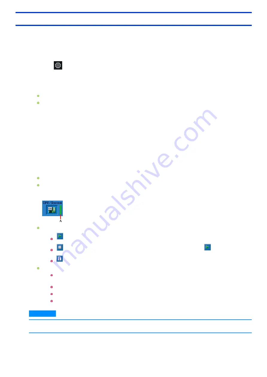
The keyboard may not be used when each hardware checking is running. While checking, a vertical green progress bar (A) is displayed
on the right side of the hardware icon.

You can perform the following operations by touching the icons on the screen:

: Start the diagnostic check from the beginning.

: Stop the diagnostic check (After the process is stopped, you cannot resume it by touching

).

: Display help (Touch the screen to return to the original screen.).

You can check the status and results of the diagnostic check via the progress bar displayed on the right of the hardware icon.

When the bar is progressing: The diagnostic check is in progress.
During memory diagnostic check, the display may stop for a long period of time. Wait until the process is complete.

When the bar is green: No problems discovered.

When the bar is red: Problems discovered.

When the bar is yellow: The diagnostic check has been stopped or is complete.

N O T E

n

Using the following procedure, you can run a diagnostic check on a specified hardware component, or run an extended dia-
gnostic check on the memory or the flash memory (The extended diagnostic check is only for the memory and the flash

-

122

-

Summary of Contents for FZ-M1 Series

Page 1: ...arks or trademarks of IntelCorporation microSDXC Logo is a trademark of SD 3C LLC MobileMark is a U S Registered Trademark of the Business Applications Performance Corporation The terms HDMI and HDMI...

Page 2: ...August 15 2004 through 1 6 3 July 18 2013 are Copyright c 2004 2006 2013 Glenn Randers Pehrson and are distributed according to the same disclaimer and license as libpng 1 2 5 with the following indiv...

Page 3: ...courage the use of this source code as a component to supporting the PNG file format in commercialproducts If you use this source code in a product acknowledgment is not required but would be apprecia...

Page 4: ...o press the Enter key Alt Del This means to press and hold Alt key and then press Del key In these instructions the names are referred as follows Windows 10 Pro as Windows or Windows 10 Multilanguage...

Page 5: ...e Notification area The notification area is on the right side of the screen To display the notification touch Notification on the task tray Latest Information on Windows 10 When Windows 10 is updated...

Page 6: ...ght sensor is used to adjust the display screen brightness automatically To configure the automatic adjustment function proceed as follows 1 Touch Settings System Display Alternatively touch Start Set...

Page 7: ...partitioned cannot be used n USB storage devices that are recognized as SCSI i e UASP 1 devices cannot be used 1 USB Attached SCSI Protocol CAUTION n USB memory device can also be used as a recovery d...

Page 8: ...discs complete screen For USB storage devices 1 Touch OK on the Allrecovery discs complete screen 2 Perform Safely Remove Hardware and Eject Media and remove the USB storage device N O T E n The disc...

Page 9: ...About the Partition Structure CAUTION n Do not add or delete partitions in Windows 10 as the Windows area and recovery partition must be adjacent to each other in Windows 10 9...

Page 10: ...follow the steps below 1 Open the Control Panel and then touch System and Security File History 2 Touch System Image Backup 3 Touch Create a system image Follow the on screen instructions N O T E n C...

Page 11: ...ction that adjusts the display screen Automatic bright ness adjustment D Front Camera Camera a Camera Lens b Camera Indicator E LED Indicators Power Indicator Off Power off Hibernation Green Power on...

Page 12: ...Security Slot A Kensington cable can be connected For further information read the manualthat comes with the cable B Expansion Bus Connector Cradle C External Antenna Connector Only for modelwith wire...

Page 13: ...or FZ M1J series models LAN Port Only for modelwith Barcode Reader Barcode Reader Only for FZ M1J series models Only for modelwith SerialPort SerialPort Only for modelwith LAN Port LAN B Built in Brid...

Page 14: ...Rear side When installed options A 3D camera Only for modelwith 3D camera B Thermography Camera Only for modelwith Thermography Camera 14...

Page 15: ...turn on the computer again n Do not perform the following operation until the drive indicator turns off Connecting or disconnecting the AC adaptor Pressing the power switch Touching tablet buttons sc...

Page 16: ...inutes when AC adaptor is connected of inactivity 5 minutes when operating on battery power of inactivity The computer automatically enters sleep 1 after 20 minutes when AC adaptor is connected of ina...

Page 17: ...ch and hold the object with your fingers or the dedicated pen optional and release it when a flame surrounding the object appears Using the dedicated pen optional We recommend placing the dedicated pe...

Page 18: ...nic PC Settings Utility Settings Touch Screen 2 Select the operation mode under Touch Screen Mode Pen mode Suitable for the dedicated pen optional operation Use this mode when not operating with finge...

Page 19: ...be used or the pen cannot be used in the Pen Pen Touch mode Calibrating the Screen Pen input and touch input are properly configured under default settings so calibration is not necessary under normal...

Page 20: ...pecify the area in which you want to perform touch operations the area is displayed in a zoom window allowing you to perform touch operations in an expanded dis play Using Touch operation support sett...

Page 21: ...ain if you select the Do not show this again checkbox and tap OK N O T E n If two points that willresult in a zoom window size that is larger than the resolution of the screen are tapped the zoom wind...

Page 22: ...indow and perform the steps in Opening the zoom window to expand the display again Additional functions Touch operation support settings include the following helpfulfunctions for when you press and h...

Page 23: ...you select the Display Operation Guides checkbox and touch OK to close the window operation guides willappear the next time you perform a two finger tap after signing in D Touch this to restore chang...

Page 24: ...de You can select on off of LCD Backlight LED Sound Wireless Radio Camera light Camera Flash 1 and Touch Screen The camera indicator cannot be turned off 1 Only for FZ M1J series models N O T E n You...

Page 25: ...hange the functions of and buttons 1 Touch Panasonic PC Settings Utility Settings Button Key 2 Touch Settings under Tablet Buttons 3 Select the Tablet button and touch Change Alternatively you can ope...

Page 26: ...here the temperature is high This computer s battery willnot be charged if its temperature is outside the allowable range At such a time the battery indicator blinks orange We recommend charging the b...

Page 27: ...e if the battery pack is stored inside a vehicle with allits windows closed and exposed to the hot sun or in other places where the temperature is high Store the battery pack where the temperature is...

Page 28: ...ning battery is approximately 9 or less Blinking red The battery pack or the charging circuit is not operating properly Remove the battery pack immediately Blinking orange The battery cannot be charge...

Page 29: ...t The battery pack can be replaced N O T E n Once the battery is fully charged the computer performs recharging only when the battery levelbecomes less than approximately 95 so over charging is avoide...

Page 30: ...he computer replace the battery and turn the computer on again When the computer enters hibernation with the battery down and you resume the operation without charging the battery the Windows Resume L...

Page 31: ...n In sleep do not remove replace the battery pack Otherwise your data will be lost and the computer may be damaged n Do not use without inserting battery pack n If the computer is wet wipe them off an...

Page 32: ...ove the battery pack forcibly when the latches are locked Doing so may damage the battery pack Only for model with Built in Bridge Battery n If the built in bridge battery has not enough remaining pow...

Page 33: ...the step 2 of Sleep setting above touch Change advanced power settings 2 Double touch Sleep and double touch Hibernate after 3 Touch the item and select the setting 4 Touch OK Precautions Connect the...

Page 34: ...suming from sleep or hibernation n Failing the password input while resuming from hibernation Entering Resuming from Sleep or Hibernation The computer automatically enters sleep after 20 minutes when...

Page 35: ...ich option is selected under the ControlPanel Hardware and Sound Power Options Choose what the power button does When I press the power button In sleep or hibernation n Do not attach or remove periphe...

Page 36: ...rt D This Application Settings E Menu Select the items When touching name of the items appears F Restore Defaults Restore the settings to the default values G Information Display help 2 Make the opera...

Page 37: ...ther information about the computer you can refer to the on screen manual Update the on screen manuals This describes the procedures to update the on screen manual Connect to a network This describes...

Page 38: ...willbe activated after restarting this application You can export or import the display items that can be used by XML files on this utility About Panasonic PC Settings Utility Display the version inf...

Page 39: ...Do not connect the telephone cable to the LAN port 1 Turn off the computer Do not use sleep or hibernation 2 Connect the cable Open the cover and connect the LAN port A and the network system e g ser...

Page 40: ...llular to On for wireless WAN set Wi Fi 1 to On for wireless LAN set Bluetooth to On for Bluetooth set GPS to On for GPS on wireless WAN set GPS GNSS to On for dedicated GPS 1 Screen messages are expl...

Page 41: ...et settings For wireless LAN Wi Fi wireless WAN Bluetooth and GPS on wireless WAN dedicated GPS 1 Touch on the task tray 2 Touch Network Internet settings Network Internet screen appears 3 Touch the m...

Page 42: ...Wireless LAN of Wireless Configuration to Enabled default in the Advanced menu of the Setup Utility Using the Wireless LAN Function Before using a wireless LAN turn the wireless LAN communication on T...

Page 43: ...the necessary information such as the network name SSID and touch Next For further information ask the system administrator or the person in charge of the network Enabling Disabling the Wireless LAN...

Page 44: ...To enable the wireless communication Disabling Enabling Wireless Communication 2 Touch Settings Network Internet Airplane mode 1 to Off 3 To turn off the Bluetooth communications set Bluetooth to Off...

Page 45: ...eless WAN is operating correctly If communication fails the device may not be recognized correctly In this case restart the computer n Do not use the microSIM card adapter n Do not insert microSIM car...

Page 46: ...pack and connect the AC adaptor To remove a SIM card 1 Turn off the computer and disconnect the AC adaptor 2 Turn over the computer Make sure no foreign objects are under the computer 3 Disconnect th...

Page 47: ...ting the SIM card Internet connection willbe possible In such cases the following settings are not necessary Adding an APN If Internet connection via wireless WAN is not possible perform the following...

Page 48: ...ion via Wi Fi n When using wireless WAN perform the following to disable Airplane mode 1 1 Touch Settings Network Internet Airplane mode 1 2 Set Airplane mode 1 to Off 3 Set Cellular to On 1 Screen me...

Page 49: ...n You can also touch on the task tray and then touch Disconnect 49...

Page 50: ...nic PC GPS Viewer To use the Panasonic PC GPS Viewer proceed the following operation 1 Touch GPS Viewer You can start up Panasonic PC GPS Viewer from Panasonic PC Settings Utility Launch Panasonic PC...

Page 51: ...used Use Sleep Touch Power Sleep to set the computer to sleep when you have to leave the computer This shuts down computer operation to reduce power consumption Only for model with LAN Disable Wake Up...

Page 52: ...ges Creating Your Own Power Setting 1 Touch and hold or on the task tray and then touch Power Options 2 Touch Create a power plan touch the basic plan and input the name of power plan 3 Touch Next 4 C...

Page 53: ...ntact Panasonic Technical Support n When running the Setup Utility do not leave and go away from your computer even for a short time since other people may set or change the password n When running th...

Page 54: ...d input willalso be required at Windows restart Same as Boot is the default setting Preventing Your Flash Memory Drive from Being Read or Written The flash memory lock function protects the flash memo...

Page 55: ...mage Recovery screen n Backups created with Create a system image are not encrypted Physically store the media on which the backup is stored in a safe location n The backup recovery procedure will com...

Page 56: ...tion Lock button allows you to lock the screen display 1 Press the Rotation Lock button A You can switch automatic rotation ON OFF by pressing the Rotation Lock button Alternatively you can switch aut...

Page 57: ...rnalLCD The computer s performance is slightly lowered The touchpad scrollfunctions do not work n While the display is set to rotate automatically the computer s performance is slightly lowered n When...

Page 58: ...ou press in succession the Concealed Mode may not be switched More than 4 seconds interval is necessary to switch on off Disabling Enabling the Concealed Mode This function is effective when the compu...

Page 59: ...lity When you start the Setup Utility with User Password Note the following In the Advanced and Boot menus you cannot make the settings of allitems In the Security menu you can change only the User Pa...

Page 60: ...OS Information BIOS BIOS Configuration Embedded Controller Intel R ME Firmware Only for FZ M1J series models Intel R TXE Firmware Only for FZ M1G series models Accumulative Operating Time Access Level...

Page 61: ...Button Disabled Application2 Ctrl Alt Del Barcode Reader Trigger Only for modelwith Barcode Reader and only when A Button is not set to Barcode Reader Trigger Rotation Lock Preboot Key Binding Key ass...

Page 62: ...OFF ON Only for modelwith Barcode Reader Barcode Reader 3 OFF ON TouchScreen 3 OFF ON 3 Can only be configured when Concealed Mode Configuration is set to Enabled OptionalKit Configuration Normally do...

Page 63: ...onfiguration SerialPort Only for modelwith SerialPort Disabled Enabled Wireless Configuration The sub menu appears when this item is selected Enter the sub menu LAN Only for modelwith LAN Disabled Ena...

Page 64: ...artup from USB devices is not possible set Compatible and retry However setting Compatible willrequire longer time to display the Windows boot screen than setting Normal Normal Compatible UEFI Priorit...

Page 65: ...ed Boot Option 5 Windows Boot Manager Recovery Partition Windows Recovery Environment UEFI PXE IP4 Realtek USB FE Family Controller 6 UEFI PXE IP6 Realtek USB FE Family Controller 6 UEFI PXE IP4 Realt...

Page 66: ...d Password On Boot The shutdown when the fast startup is enabled this function is ineffective Disabled Enabled Password On Reboot Disabled Same as Boot Password On Resume Can be changed only when Pass...

Page 67: ...r the sub menu Secure Boot The sub menu appears when this item is selected If you change factory default setting preinstalled OS may not operate correctly Enter the sub menu Exit Menu Save Values and...

Page 68: ...s designed to minimize shock to parts such as the LCD and the flash memory drive and equipped with a drip proof keyboard but no war ranty is provided against any trouble caused by shock Be extremely c...

Page 69: ...Manualto avoid any damage to the devices Carefully read the instruction manuals of the peripheraldevices Use the peripheraldevices conforming to the computer s specifications Connect to the connector...

Page 70: ...an automatic brightness adjustment function that adjusts the display screen based on the ambient light sensor You can configure the automatic adjustment function as follows 1 Touch Settings System Dis...

Page 71: ...ot use force since the LCD sur face may be damaged with the foreign particles or dust Next wipe off fingerprint etc with the other side of the soft cloth After wiping off foreign particles and dust wa...

Page 72: ...ers and cosmetics as they may contain components harmfulto the surface n Do not apply water or detergent directly to the computer since liquid may enter inside of the computer and cause malfunction or...

Page 73: ...he card before the oper ation is completed the data may be damaged or the card access may no longer be performed normally n Note that Panasonic assumes absolutely no liability for any loss of data rec...

Page 74: ...n the AC adapter is connected it is not necessary to turn off the computer 3 Turn over the computer and remove the battery pack Replacing the Battery Pack Make sure no foreign objects are under the co...

Page 75: ...t location for a long time Remove the card immediately after inserting it Inserting Removing the Smart Card To insert the card 1 Slide the cover A 2 Open the cover A and insert the Smart Card B to the...

Page 76: ...To remove the card 1 Draw the card straight out 2 Close the cover 76...

Page 77: ...Remove the card immediately after inserting it Reading Magnetic Stripe Card Insert the magnetic tape part of the card into this unit s card reading part and slide it Face the magnetic tape of the car...

Page 78: ...asonic PC Settings Utility Utilities Barcode HID Language Setting 2 Set the language of the barcode reader according to the Default Input Local SUCCESS on screen appears 3 Touch OK Alternatively touch...

Page 79: ...eads barcode with 2 bytes code 1 Touch Panasonic PC Settings Utility Utilities 2D Barcode Key Emulator 2 Touch Connection to Barcode Always On 3 Open the software for reading a barcode and put the cur...

Page 80: ...rform reading so that the entire symbol falls within the center of the red Barcode Reader light The reader can still read a barcode even if the barcode is not in the center of the red Barcode Reader l...

Page 81: ...gy type of barcode 1 Touch Symbology Configuration tab 2 To deploy the symbology you want to set 3 Select Disable or Enable in ACTIVATE If you can set up a data editing function of barcode reader 1 To...

Page 82: ...code configuration file 2 Touch Tool Apply Configuration 6 Touch File Exit At the confirmation message select Yes Direct application of the barcode configuration file 1 Create the barcode configuratio...

Page 83: ...n the settings some external displays may be distorted or may not display the mouse pointer correctly In this case set the settings to lower value n When you use the simultaneous display MPEG files an...

Page 84: ...y screen with touch operation n Set the internal LCD to the primary display when using the screen The pointer will move on the primary display when you touch the internal LCD To Change the Sound Outpu...

Page 85: ...off the computer is not displayed The device does not appear in the list in step 2 2 Remove the USB device CAUTION Only for model with Smart Card slot n If you double touch USB Smart Card Reader is di...

Page 86: ...e remove and connect the device again or restart the computer n When a USB device is connected power consumption increases Remove the USB device when it is not in use especially when operating by bat...

Page 87: ...vice 1 Connect the cable Open the cover A and connect the serialconversion cable B included to the serialport C 2 Connect the serial device to the connector of the serial conversion cable N O T E n Wh...

Page 88: ...you use this utility and other multi media software at the same time an error may occur Close allmulti media software including this utility and restart this utility n If an error message appears and...

Page 89: ...n storage space is less than 10 MB Start Stop shooting videos 1 Touch The camera switches to the video shooting mode 2 Touch During shooting the icon is shown as 3 To stop shooting touch If the save d...

Page 90: ...Display the recorded image or video files 1 Touch The recorded data willbe saved in the displayed folder named the recording date Only for model with rear camera 90...

Page 91: ...Other Functions 91...

Page 92: ...age pack is necessary in order to use the OCR feature of other languages If it is not installed please download the language pack by the following pro cedure 1 Touch Settings Time Language Region lang...

Page 93: ...e the barcode text Turn the light ON OFF You can turn on off the light Turn off the light Turn off the light Flash available Turn on the light Only for model with multiple cameras Switch camera Switch...

Page 94: ...e resolution Perform touch operation or mouse click to select the resolution The resolution may not be correctly specified if you use the keyboard cursor keys H Video resolution Change the video resol...

Page 95: ...is the Pictures OCR folder Q Self Timer Specify the time period untilshooting starts after the button is pressed OFF 5 sec 10 sec R Interval Shooting When you move the slider to the right and specify...

Page 96: ...is typically used with specialized applications For further information ask the system administrator 1 Align the RFID tags Smart Card with the mark A and wave the RFID tags Smart Card A Smart Card can...

Page 97: ...eries and FZ VEBM12 series Illustrations of FZ VEBM12 series are used For parts provided only for a specific model the modelnumber is shown Names and Functions of Parts CAUTION n Do not touch the expa...

Page 98: ...s security slot after the computer is connected the computer cannot be disconnected because the lever is locked For more information read the manualthat comes with the cable L DC IN Jack Connecting Di...

Page 99: ...does not come off the cradle n If the computer malfunctions while the Cradle is attached disconnect the Cradle and check to see if the computer operates normally If the computer operates normally the...

Page 100: ...ecting Disconnecting the Computer the battery attached to the computer is automatically charged Charging the battery pack attached to the Cradle Only for FZ VEBM12 series 1 Connect the AC adaptor to t...

Page 101: ...temperature is out of the acceptable range The power supply is not enough because software applications or peripheraldevices are consuming a large amount of power N O T E n If you set Battery Charging...

Page 102: ...t there is no item under the computer 1 Pass the belt which has an adjuster A through the strap hole located on the left side of the back of the computer 2 Pass the belt through the adjuster and secur...

Page 103: ...r Attaching the tether to the hand strap 1 Pass one of the loops through the hole 2 Pass one of the loops through another loop 3 Pass the loop through the ring of the hand strap 4 Pass the pen and tet...

Page 104: ...ecessary CAUTION n If the hand is not securely fixed to the hand strap the computer may drop When the hand strap is too loose or too tight you can adjust the hand strap according to the instructions b...

Page 105: ...Velcro straps part of the hand strap 2 Raise the right side of the hand strap With the right side of the hand strap lifted up insert remove the battery pack For information about remove the battery pa...

Page 106: ...cover C Rear cover Installing the shoulder case 1 Remove the Velcro tape on the hand strap of the case body and then pull out the belt 2 House the computer in the case with the screen facing downward...

Page 107: ...y pack is mounted adjust the Velcro tape position 4 Attach the rear cover to the case body using the Velcro tapes Attach the tapes firmly so that they do not come off N O T E n If optionalitems are at...

Page 108: ...the case body using the Velcro tape 7 Attach the Velcro tapes on both sides of the front cover to the case body cover N O T E n When using the computer remove the front cover or fold as shown below n...

Page 109: ...4 C AC adaptor ModelNo CF AA6503A D AC cord CAUTION n The AC cord may vary depending on the country Indicators The power indicator on the battery charger lights green when the power is being supplied...

Page 110: ...lights when the battery pack is properly inserted with the AC adaptor connected Four battery packs can be inserted simultaneously Each of them can be inserted in any slot When removing the battery pa...

Page 111: ...mperature for about an hour and then turn on the power again Cannot turn on the computer The computer does not resume from sleep The battery indicator blinks green and orange alternately The power ind...

Page 112: ...or 1 Remove allperipheraldevices including an externaldisplay 2 Touch Allapps Windows System This PC 3 Touch and hold Windows C and touch Properties 4 Touch Tools Check A standard user needs to enter...

Page 113: ...while the computer was in sleep If the computer s power supply is disconnected in sleep unsaved data willbe lost and the computer willnot resume The battery is exhausted Sleep and hibernation consumes...

Page 114: ...ss of the picture elements may be dark or remain constantly lit i e more than 99 998 of elements function properly Due to the naturalcharacteristics of LCD screens you may notice unevenness in colors...

Page 115: ...ten Input Characters Cannot enter specialcharacters etc and symbols Use the character map 1 Touch Allapps Windows Accessories Character Map 2 Input Character Network Only for modelwith LAN Cannot conn...

Page 116: ...nfirm the following settings Wireless WAN in the Advanced menu of the Setup Utility Confirm that Wireless WAN of Wireless Configuration is set to Enabled Airplane mode 1 Confirm that Wireless WAN Cell...

Page 117: ...emove the check mark for Allow the computer to turn off this device to save power in Power Management This item may be unavailable for some types of devices In the case that a USB device does not work...

Page 118: ...nd driver Barcode Reader only for model with Barcode Reader Reading is not possible Confirm that the barcode is readable without damage etc Confirm that the barcode sym bology is readable If the barco...

Page 119: ...ormation Viewer You may need this information when calling Panasonic TechnicalSupport for advice N O T E n This computer periodically records the management information of the flash memory etc The max...

Page 120: ...he file name and then touch Save To save a copy of the screen as an image file To save a copy of the screen as an image file perform the following steps 1 Display the screen you want to save 2 Press a...

Page 121: ...y for modelwith serialport Only for FZ M1G series models Wireless WAN Only for modelwith wireless WAN Bluetooth Only for modelwith Bluetooth GPS Only for modelwith dedicated GPS 1 When the PC Diagnost...

Page 122: ...uter willrestart 5 Touch the top left corner of the screen several times to display Setup Utility 6 Touch Exit menu and then double touch Diagnostic Utility When the PC Diagnostic Utility starts up it...

Page 123: ...stic check results If the display is red and the message TEST FAILED is displayed you can assume that there is a problem with the computer s hardware Con firm which hardware component is displayed as...

Page 124: ...fully cleaning the deleted files cannot be recovered easily and the security levelwillbe increased The processing time willbe longer Approximately 50 minutes 4 Follow the on screen instructions After...

Page 125: ...ard etc Connect the AC adaptor and do not remove it untilinstallation is complete 1 Start the Setup Utility 1 Touch Settings Update Security Recovery 2 Touch Restart now under Advanced startup 3 Touch...

Page 126: ...n using DVD media to create a recovery disc prepare the commercially available opticaldrive Remove allperipherals excluding the device that was used to create the recovery disc Connect the AC adaptor...

Page 127: ...oot Follow the on screen instructions 15 On the Finish Recovery Process screen touch Shutdown 16 Turn on the computer 17 Perform Setup Windows OPERATING INSTRUCTIONS Read Me First 18 Start the Setup U...

Page 128: ...oblem persists the internalclock battery may need to be replaced Contact Panasonic TechnicalSupport Press F2 for Setup Write down the error details and start the Setup Utility Change the settings if n...

Page 129: ...wing steps the fast startup willbe disabled at next boot up 1 Touch Settings Update Security Recovery 2 Touch Restart now under Advanced startup 1 3 Touch Turn off your PC 1 Screen messages are explai...

Page 130: ...e specified partition However the entire flash memory drive data including the data of the partition with recovery tools willbe erased n The erasing disk menu is not displayed when using the recovery...

Page 131: ...e or USB storage device in Boot Override The computer willrestart 8 Touch Erase 9 Touch Erase the all data on the whole Disk 10 Touch Start Erase Process Erasing the flash memory drive data starts 11...

Page 132: ...e battery Attention Qualified professionals to remove the battery Dispose of this product correctly in accordance with the localregulations after removing the battery as shown in the following procedu...

Page 133: ...4 Pull out all cables from the connector on the cover side 5 Dispose of the battery with the cover attached correctly in accordance with the local regulation 133...

Page 134: ...tel HD Graphics 615 Premium Built in Chip Set Only for FZ M1G series models Intel UHD Graphics 600 Built in Chip Set Main Memory 1 2 Only for FZ M1J series models 4 GB 8 GB on board LPDDR3 Only for FZ...

Page 135: ...U95W Optional Operating Time 11 Only for FZ M1J series models Approx 8 hours with FZ VZSU94W Approx 18 hours with FZ VZSU95W Optional Only for FZ M1G series models Approx 10 hours with FZ VZSU94W Appr...

Page 136: ...r FZ M1J series models Intel RealSense Calibration Tool 25 Aptio Setup Utility PC Diagnostic Utility Hard Disk Data Erase Utility 26 Wireless LAN 5 Data Transfer Rates 27 IEEE802 11a 54 Mbps IEEE802 1...

Page 137: ...function 5 Only for modelwith wireless LAN 6 Only for modelwith Bluetooth Does not guarantee operation of allBluetooth peripherals 7 The specifications may differ depending on the model Depending on...

Page 138: ...efore use 20 For localized OS model For information on Wireless Manager refer to the Supplementary Instructions by the following procedure 1 Touch and hold Start at the bottom left corner 2 Touch Run...

Page 139: ...3 Check the model number The model number C starting with FZ M1 is described 139...

Page 140: ...es not affect functionality is not covered Cosmetic damage on Products with hardware failures willbe repaired in accordance with the warranty terms This warranty is extended solely to the originalpurc...

Page 141: ...in materialand work manship under normaluse for a period of sixty 60 days from the date of delivery thereof to you as evidenced by your purchase receipt This is the only warranty Panasonic makes to y...

Page 142: ...LIED WARRANTIES INCLUDING THE WARRANTIES OF MERCHANTABILITY AND FITNESS FOR A PARTICULAR PURPOSE ARE LIMITED TO THE APPLICABLE WARRANTY PERIOD SET FORTH ABOVE Some states do not allow the exclusion or...

Page 143: ...he copy of the software for any software warranty claim Claim Procedure In the event of a defect in materialor workmanship in the media during the sixty 60 days warranty period and you return it trans...

Page 144: ...un cas fortuit ou une r paration effectu e par une personne non agr e par PCI CE PRODUIT N EST PAS DESTIN TRE UTILIS EN TOUT OU EN PARTIE COMME SYST ME QUIPEMENT NUCL AIRE SYST ME QUIPEMENT DE CONTR L...

Page 145: ...te of originalpurchase in the event of a defect in materials or workmanship This warranty only applies to new Panasonic Toughbooks purchased in the EEA and Switzerland and Turkey Panasonic or its auth...

Page 146: ...y and your exclusive remedy under this warranty shallbe limited to the replacement of any defective disk or other media which is returned to Panasonic s authorized Service Centre together with a copy...

Page 147: ...93 Switzerland German 41 0 800 002429 Switzerland French 41 0 800 588017 E mailaddress toughbooksupport eu panasonic com Czech speaking service 420 0 800 143234 Hungarian speaking service 36 0 6800 16...

Reviews: