background image

3

Table of Contents

1.

Product Outline  .......................................................................................... 5

1.1. Features  ................................................................................................. 5
1.2. LED Behavior  .......................................................................................... 6

1.2.1.LED Behavior during Start-up ............................................................. 6
1.2.2.LED Behavior while Operating  ........................................................... 7
1.2.3.Operation Overview of PoE Power Supply Function  ........................... 9

2.

Installation  ............................................................................................... 10

3.

Connection  .............................................................................................. 11

3.1. Connecting a Twisted Pair Port ............................................................. 11
3.2. Connecting to Power  ........................................................................... 12

4.

Web Browser-based Control ..................................................................... 13

4.1. Operating Environment  ........................................................................ 13
4.2. IP Address Configuration ...................................................................... 14
4.3. Access to Web Control Function  ........................................................... 15
4.4. Displaying Basic Information ................................................................. 17

5.

Switch Configuration  ............................................................................... 19

5.1. Basic Config  ......................................................................................... 19

5.1.1.Administration Config  ..................................................................... 19
5.1.2.IP Config  ......................................................................................... 20
5.1.3.Basic Port Config ............................................................................. 21
5.1.4.Extend Port Config  .......................................................................... 23
5.1.5.Power Saving Config  ....................................................................... 24
5.1.6.System Security  ............................................................................... 25
5.1.7.Syslog Transmission Config  ............................................................. 26
5.1.8.ID/Password Change ....................................................................... 27
5.1.9.FDB Table ........................................................................................ 28
5.1.10.Time Config  .................................................................................. 29
5.1.11.Static ARP Table ............................................................................ 30
5.1.12.ARP Table  ..................................................................................... 31

5.2. Advanced Switch Configuration  ........................................................... 32

5.2.1.VLAN Management  ........................................................................ 32

5.2.1.a.

VLAN Modification  ............................................................... 34

5.2.2.VLAN Creation  ................................................................................ 35
5.2.3.VLAN Port Config ............................................................................ 36
5.2.4.Traffic Class Config .......................................................................... 37
5.2.5.Diffserv Config  ................................................................................ 38
5.2.6.Link Aggregation Config  ................................................................. 39

5.2.6.a.

Link Aggregation Modification  ............................................. 40

5.2.7.Storm Control Config  ...................................................................... 41
5.2.8.Port Monitoring Config  ................................................................... 42
5.2.9.Static Multicast Address Config  ....................................................... 44

Summary of Contents for GA-AS16TPoE+

Page 1: ...WEB Reference Layer 2 Switching Hub Model No PN25161 PN25168 PN25241 PN25248 PN25481 PN25488...

Page 2: ...E PN25248 TH PN25248 MY PN25248 ID PN25248 SG PN25248 NZ 1 0 0 07 and above GA AS48TPoE PN25488 TH PN25488 MY PN25488 ID PN25488 SG 1 0 0 10 and above GA AS16T PN25161 TH PN25161 MY PN25161 ID PN25161...

Page 3: ...Basic Config 19 5 1 1 Administration Config 19 5 1 2 IP Config 20 5 1 3 Basic Port Config 21 5 1 4 Extend Port Config 23 5 1 5 Power Saving Config 24 5 1 6 System Security 25 5 1 7 Syslog Transmission...

Page 4: ...52 5 3 2 Reboot 53 5 3 3 Save Current Config 54 5 3 4 Statistics 55 5 3 5 System Log 58 5 3 5 a System Log Config 62 5 3 6 Config File Transfer 63 5 3 7 Ping Execution 64 5 3 8 Exception Handler 65 5...

Page 5: ...r the target is a terminal or a network device By factory default downlink ports are fixed to MDI X The IEEE802 3az LPI compatible Energy Efficient Ethernet EEE function is sup ported allowing reducti...

Page 6: ...ing Start up When you turn on this switch all LEDs are lit momentarily Then self diagnosis of the hardware is conducted When the self diagnosis is com pleted the STATUS LED is lit in green and the har...

Page 7: ...TATUS LED Green light System operating normally Orange light System starting up Orange blink System failure PoE LIM LED PoE supported devices only Off Supplies power in the range of GA AS16TPoE 0 to 1...

Page 8: ...n light Link established Green blink Transmitting data Off No device connected Right PoE Green light Supplying power normally Green blink The whole unit or the single port is overloaded Off Not supply...

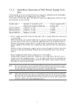
Page 9: ...rts is set as the same Power supply operation when a single port is overloaded When power request exceeds the maximum on a single port the port is over loaded and stops supplying power You can check w...

Page 10: ...10 2 Installation For the installation methods for each model refer to the operating instructions...

Page 11: ...hen a terminal or a device without auto negotiation function is connected to a port this switch automatically determines and sets the communica tion speed however the full duplex half duplex configura...

Page 12: ...of this switch and connect the power plug into an electric outlet The switch operates at AC 100 240 V 50 60 Hz It does not have a power switch When you connect the power plug the switch turns on and...

Page 13: ...tters numbers and symbols that can be used for setting are as follows ABCDEFGHIJKLMNOPQRSTUVWXYZ abcdefghijklmnopqrstuvwxyz 1234567890 _ The example setting screen used in this document may differ fro...

Page 14: ...et as factory default To access the Web con trol function screen for this switch you need to use the ZEQUO assist Plus applica tion that can be downloaded from HP with the switch to set the IP address...

Page 15: ...s switch shown in Figure 4 1 is displayed Enter the user name and password The factory default user name is manager and password is manager Figure 4 1 Login Screen Note If the login screen is not disp...

Page 16: ...ou can perform on this screen 1 General Information Displays a list of basic information of this switch 2 Basic Config Configure the basic settings such as IP address and port settings 3 Advanced Conf...

Page 17: ...17 4 4 Displaying Basic Information Select General Info to open the screen shown in Figure 4 3 This screen displays a list of this switch s basic information Figure 4 3 General Info...

Page 18: ...ere in accordance with Section 5 1 1 Administra tion Configuration Host Name Displays the switch name The factory default setting is blank For configuration details refer to Section 5 1 1 System Addre...

Page 19: ...Config 5 1 1 Administration Config Select Basic Config and then Administration Config to open the screen shown in Figure 5 1 Select this screen to display this switch s information On this screen you...

Page 20: ...gate way which are the same for other devices on the same subnet using this switch If you are unsure consult the network administrator MAC Address Displays the MAC address of this switch This value is...

Page 21: ...Select Basic Config and Port Config and then Basic Port Config to open the screen shown in Figure 5 3 On this screen you can display status and configure mode and other settings for each port Figure 5...

Page 22: ...ll duplex half duplex settings For all ports the factory default setting is Auto Auto Auto negotiation mode 10M Half 10 Mbps half duplex 10M Full 10 Mbps full duplex 100M Half 100 Mbps half duplex 100...

Page 23: ...creen Description Global Jumbo Status Displays the jumbo frame settings For all ports the factory default setting is Disable Enable The jumbo frame is enabled Disable The jumbo frame is disabled Port...

Page 24: ...isplays the current link status Up A link has been established successfully Down A link has not been established Power Saving Mode Indicates the power saving mode configuration status For all ports th...

Page 25: ...ious settings for accessing this switch for configuration and management Figure 5 6 System Security Screen Description IP Setup Interface Status Displays the access settings for the IP address configu...

Page 26: ...ystem logs to the Syslog server Disabled Does not send system logs to the Syslog server Index Displays the entry number for the Syslog transfer Status Displays the status of Syslog Transmission The fa...

Page 27: ...user name and password You need them to login to this switch Current User ID Enter the current user name This is used to login to this switch The factory default setting is manager Current Password En...

Page 28: ...the time for which an automatically learned FDB entry is retained It is equal to the time after receiving the last packet The factory default setting is 300 seconds 5 minutes Narrowing down VLAN Narr...

Page 29: ...n function set the SNTP server to 0 0 0 0 Time Zone Displays the time zone Daylight Saving Displays the application status of Daylight Saving Summer time In case the set time zone is a zone where Dayl...

Page 30: ...sociate the IP address and MAC address and register that relationship to the ARP table Figure 5 11 Static ARP Table Screen Description IP Address Enter the IP address of the ARP table to be added MAC...

Page 31: ...s Order by Sorts the list in a specified order IP Sorts the list by IP address MAC Sorts the list by MAC address Narrowing down Narrows down and displays the ARP entries Static Displays the ARP entrie...

Page 32: ...disabled Factory default setting Internet Mansion When checked communication to any port except uplink ports will be limited You can specify up to two uplink ports VLAN Total Count Displays the numbe...

Page 33: ...gement VLAN Indicates whether the VLAN is a management VLAN or not Up Indicates that the VLAN is a management VLAN VLAN that can communicate with the CPU Down Indicates that the VLAN is not a manageme...

Page 34: ...can modify the VLAN configuration information Figure 5 14 VLAN Modification Screen Screen Description VLAN ID Displays the VLAN ID VLAN Name Displays the VLAN name Untagged Port Indicates ports that...

Page 35: ...hown in Figure 5 15 On this screen you can create a new VLAN Figure 5 15 VLAN Creation Screen Screen Description VLAN ID Set the VLAN ID VLAN Name Set the VLAN name Member Port Select ports that you w...

Page 36: ...ort VLAN ID that has been set to the port PVID represents a VLAN ID to which an untagged packet should be sent when it is received The factory default setting is 1 If a tagged packet is received the t...

Page 37: ...n you can configure the QoS and Traffic Class settings Figure 5 17 QoS Config Screen Description QoS Displays Enable Disable of the QoS function using IEEE802 1p The factory default setting is Disable...

Page 38: ...n you can configure the Diffserv set tings Figure 5 18 Diffserv Settings Screen Description Diffserv Status Displays Enable Disable of the Diffserv function The factory default setting is Disable Enab...

Page 39: ...the screen shown in Figure 5 19 On this screen you can configure the group settings of link aggregation Figure 5 19 Link Aggregation Config Screen Description Group Displays the group number of the l...

Page 40: ...Mod ify button of each group to open the screen shown in Figure 5 20 On this screen you can modify the link aggregation Figure 5 20 Link Aggregation Modification Screen Description Key Displays the gr...

Page 41: ...abled The Unknown unicast storm control is enabled Disabled The Unknown unicast storm control is disabled Factory default setting Broadcast Enables or disables the broadcast storm control Enabled The...

Page 42: ...number of a port used to monitor packets for another port Monitor Target Port Indicates a port number of a port being monitored The factory default setting is 2 Monitor Direction Displays which of tr...

Page 43: ...43 Note Administrative packets such as Ping and ARP transmitted by this switch can not be captured...

Page 44: ...if VLAN Status is enabled Multicast Group MAC Address Specifies the MAC address of the multicast group Group Member Ports Specifies the ports included in the multicast group Narrowing down VLAN Speci...

Page 45: ...E Port Config Select Advanced Config and PoE Config and then PoE Port Config to open the screen shown in Figure 5 24 On this screen you can configure the power supply settings by port Figure 5 24 PoE...

Page 46: ...f power exceeding the limit is supplied by PoE Class Displays the Class value detected by the classification function Priority Displays the priority for supplying power Critical Represents the highest...

Page 47: ...s Figure 5 25 PoE Global Configuration Screen Description Power Budget Displays the maximum amount of power this switch can supply Power Consumption Displays the amount of power currently supplied by...

Page 48: ...t a time Click the Select All button and all ports will be selected Click the Reset button and all ports will be deselected Click the Set selected port s button after selecting and changing the items...

Page 49: ...When the Switching Hub detects loop the ports becomes link down It uses to take event of Link up and Link down When Recovery Status is enabled after Recover Timer Default 60 seconds 30 seconds the por...

Page 50: ...me Displays the time when the loop detection event occurred Event Displays the description of the loop detection event that occurred on this switch The loop detected on port X Indicates that a loop wa...

Page 51: ...ame group Each port can be assigned to mul tiple port groups Figure 5 28 Port Group Settings Screen Description Port Group ID Displays a port group ID Port Group Name Displays the name of the port gro...

Page 52: ...te the firmware you must save the configuration information in accordance with Section 5 3 3 Unless you save the configuration informa tion the settings configured so far will be deleted upon restart...

Page 53: ...the settings after reboot is completed Reboot Option Displays the reboot method The factory default setting is Normal Normal Normal reboot is executed Factory Default All settings are reset to factor...

Page 54: ...his screen you can save configuration information Figure 5 31 Save Current Config Click Save to save this switch s settings to its internal RAM Unless you save the configuration information the settin...

Page 55: ...een you can check the statistics Figure 5 32 Statistics Screen Description Target Port Number Displays the port number Time Displays the time elapsed since power on or counter reset Counter Name Displ...

Page 56: ...greater than 9216 bytes Fragments Displays the number of error packets that have a packet length less than 64 bytes and have a CRC or alignment error Jabbers Displays the number of error packets that...

Page 57: ...per second average of the counter for each port is displayed on the screen Figure 5 33 Statistic Information of each Counter by Port Screen Description Port Number Displays the port number Total Disp...

Page 58: ...Log to open the screen shown in Figure 5 34 This screen displays the logs of events that occurred on this switch By viewing events you can keep track of activities that occurred on this switch which a...

Page 59: ...ts enable disable of the system log for each operation For configuration details refer to Section 5 3 5 a Get Techni cal Informa tion Download the technical information as text file Time Displays the...

Page 60: ...uration 1 and 2 were resetted to fac tory default setting Copy confgiuration 2 to 1 is failed Indicates that failed to copy configuration 2 to configuar tion 1 Copy configuration 1 to 2 is failed Indi...

Page 61: ...The loop detected on portX Indicates that a loop was detected in Port X The loop detected between portA and portB Indicates that a loop was detected between Port A and Port B PortX auto recovery Indic...

Page 62: ...abled Saves the system log when link goes up down Disabled Does not save the system log when link goes up down PoE ON OFF Displays the status of saving the system log when the PoE power supply status...

Page 63: ...es Figure 5 36 Config File Transfer Screen Description To save the configuration file to the TFTP server select Save to TFTP Server To load the configuration file into this switch select Load from TFT...

Page 64: ...Figure 5 37 Ping Execution Screen Description Target IP Address Displays the IPv4 address of the target of the ping The factory default setting is blank Number of Request Displays the number of times...

Page 65: ...n shown in Figure 5 38 On this screen you can configure the exception handler Figure 5 38 Exception Handler Screen Description Exception Handler Displays the exception handling function status Enabled...

Page 66: ...he screen shown in Fig ure 5 39 On this screen you can configure the Watchdog Timer settings Figure 5 39 Watchdog Timer Screen Description Watchdog Timer Displays the status of the Watchdog Timer func...

Page 67: ...for each model Flow control IEEE802 3x full duplex Back pressure half duplex Major functions IEEE802 1Q Tag VLAN 256 VLANs max IEEE802 3ad Link aggregation Refer to the Specifications for each model...

Page 68: ...Specifications for each model Weight Refer to the following Specifications for each model Specifications for each model if PoE power feeding is less than 80 watts Product Name GA AS16T GA AS16TPoE Pr...

Page 69: ...8W Operating Temperature 0 to 50 deg C 0 to 40 deg C 0 to 50 deg C Dimensions H x W x D mm 44 x 330 x 230 Weight 3 150g 3 800g Product Name GA AS48T GA AS48TPoE Product Number PN25481 PN25488 Number...

Page 70: ...subnet mask and default gateway Restrictions The time for accepting setting changes is limited to 20 minutes after power on to ensure security However you can change settings regardless of the time l...

Page 71: ...ocking func tion to a downstream Switching Hub and a loop failure occurs in the Switching Hub the downstream Switching Hub port that caused a loop is blocked to prevent a loop failure from affecting t...

Page 72: ...y the port having a loop on the Switching Hub Figure 6 2 Notes when using the Loop detection and blocking function Notes when using the Loop detection and blocking function Disable the function on the...

Page 73: ...2 12 7 Higashi Shimbashi Minato ku Tokyo Japan 105 0021 URL https panasonic co jp ew pewnw english index html P0217 6052 Panasonic Electric Works Networks Co Ltd 2017 2022...

Reviews: