background image

Page 15 of  17

Model
Name

Model
No.

GA-M+

PN260496-TH

Product Specification

401-260496-TH-SP05

Date issued

Date revised

Jun. 29, 2021

Apr. 1,2022

Panasonic Electric Works Networks Co., Ltd.

Denotes that “Minor injuries might be sustained, or property damage might occur”.
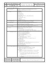
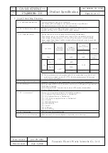
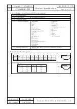
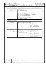
The manufacturer assumes no responsibility for any problems occurring when the following conditions are not satisfied.
Observe the following items when using the product.

(1) Use the bundled power cord (AC 100 – 240 V specifications).

Deviation could lead to electric shock, malfunction, and/or equipment failure.

(2) Unplug the power cord in case of equipment failure.

Deviation, such as keeping connected for a long time, could lead to fire.

(3) Be sure to connect the ground cable.

Otherwise this might cause electrical shocks, misoperations and malfunctions.
Connect the Ethernet Switch via the supplied power cord to the outlet which is connected to the ground.
If the outlet is not connected to a ground, connect the ground cable to the ground terminal screw.

(4) Connect the power cord firmly to the power port.

Otherwise this might cause electrical shocks and malfunctions.

(5) Unplug the power cord if the STATUS/ECO LED (Status/ECO mode) or FAN LED (Fan sensor) 

blinks in orange (system fault).

Deviation, such as keeping connected for a long time, could lead to fire.

(6) Handle the Ethernet Switch carefully so that fingers or hands may not be damaged by twisted pair port, SFP extension slot,  

console port or power cord hook block.

(7) When mounting the Ethernet Switch on a wall, mount it securely using wall mount brackets to prevent the Ethernet Switch from

falling due its weight and that of the connection cables.

Deviation could lead to falling, injury and/or equipment failure.

(8) If the device is going to be mounted onto a rack, use the 2 installation brackets(for 19-inch rack mounting) which include 

the 19 inch rack mounting brackets (for 1 rack) and the 8 screws (for the rack installation brackets and for 
the main unit connections), and install the installation brackets into each of the 4 horizontal holes in the device, 
then securely secure it and set it up.

If it is not firmly secured, then deviation could lead to falling, injury and/or equipment failure.

(9) Up to two Ethernet Switches can be connected by using the connection brackets and connection bracket screws. 

Attach the connection brackets to the connection bracket screw holes on the front and back panels to securely fix the Switching 
Hubs before installation.

If the Ethernet Switches are not fixed securely, they may fall, leading to injury and/or equipment failure.

(10) Check whether the optical fiber cable connectors are contaminated with dust, etc.

This might cause the optical signal to not be transmitted normally, and cause misoperations and malfunctions. If they are 
contaminated, make sure to clean them off, then connect them to the optical fiber ports.

(11) This Ethernet Switch is to be periodically serviced in order to maintain its performance.

Please choose a product administrator, and have them be sure to implement periodic maintenance. When doing maintenance, 
check the inspection chart that is posted on our website which has the requisite items listed on it.

(12) When using this Ethernet Switch to design systems, use it after applying appropriate measures such as setting up redundant 

configurations.
Communications failures might be generated due to causes such as malfunctions or misoperations while the Ethernet Switch is 
being used.

(13) When using this Ethernet Switch for applications which require extremely high reliability, be careful to expend all possible means 

to ensure safety and reliability.
This Ethernet Switch was not designed nor manufactured with the intention that it be used for applications (in use with railways, 
aviation, and medical care, etc. whereas the influence rate due to communications failures is extremely high in regard to systems 
that directly affect systems and human lives) which require extremely high reliability.

13. Cautions when Using the Product to Guarantee Safety

Summary of Contents for GA-ML4TWPoE++

Page 1: ...regation Ports 1 to 4 are set at MDI X default 6 Telnet SSH allows remote configuration changes and verifications of the Ethernet Switch Remotely configure the PoE settings for each port Ports 1 to 4 7 The connection status for each port is detected by the power saving mode and it can suppress the power consumption to required volumes when not linked up Factory default deactivated 8 Rapid Spanning...

Page 2: ...n the upper limit for the operating environmental temperatures may change For details check 7 11 The Silent Fan Control Functions 3 4 Storage environment Temperature 20 70 Humidity 10 90 RH no condensation Normally Max 291W 15 7W when not supplying power Min 11 5W 3 Rated Environmental Conditions 4 1 Form and materials colors 4 2 Mass Weight 2 300g 4 Form Dimensions 44mm Height 210mm Width 260mm D...

Page 3: ... used Twisted pair port RJ45 connector Port 5 to 6 1 Transmitting and receiving network system IEEE802 3 10BASE T IEEE802 3u 100BASE TX IEEE802 3ab 1000BASE T energy efficient Ethernet IEEE802 3az LPI Transmission speed 10 100 1000Mbps full half duplex Compatible cable Twisted pair cable At least equivalent to EIA TIA568 category 5e Maximum transmission distance 100m Auto Negotiation Communication...

Page 4: ...x 1 488 000pps port 1000Mbps Max 148 800pps port 100Mbps Max 14 880pps port 10Mbps MAC Address table Max 16K entry unit Automatic learning can be enabled disabled for each port Fixed registration is enabled Buffer memory 2 0M Bytes unit Flow control half duplex Back pressure full duplex IEEE802 3x Aging timeout 10 to 1 000 000 sec Default 300 sec Jumbo frame supported 9KB Transmittable frames EAP ...

Page 5: ... is exceeding the upper limit or the total power supply of the Ethernet Switch is exceeding 180 W 3 TEMP Temperature sensor LED Green Light The system is normally operating Orange Blink The temperature exceeded the set threshold of the internal temperature sensor Set threshold of the internal temperature sensor 79 factory default 4 FAN Fan sensor LED Green Light The system is normally operating Or...

Page 6: ...s light up at the same time When you release the button the Base mode is changed to the selected mode If the mode is changed to the GIGA mode DUPLEX mode or Loop History mode and the LED display switch button is not used for one minute or longer the mode automatically returns to a Base mode Status mode or ECO mode The Base mode is maintained even after the power is turned OFF LED display change bu...

Page 7: ...plied or the PoE receiving equipment are not connected also it is set in the ECO mode Table 1 Display mode Behavior Description STATUS ECO GIGA FULL LOOP HISTORY Link is established Transmitting and receiving data It is shut off via the loop detection and shut off function storm control or the BPDU guard It is sending and receiving just the control packet No device connected or the ECO mode is set...

Page 8: ... set by the following procedures 1 Configuration from an asynchronous terminal connected to the console port 2 Configuration from a remote terminal connected via TELNET and SSH 3 It can be set from a remote terminal according to the Web screen Management protocol SNMP v1 v2c v3 RFC 1157 RFC 1901 RFC 3411 RFC 3412 RFC 3413 RFC 3414 RFC 3415 RFC 3416 TELNET RFC 854 RFC 855 SSH v2 RFC 4252 RFC 4253 R...

Page 9: ...e Port LED lights up orange and the port shuts off Loop history retention time 3 days The LOOP HISTORY LED blink for three days The Port LED also remains lit for three days after the loop is eliminated Loop shutoff mode has the following 2 types of modes Block mode factory default setting When loops are detected the port statuses are automatically blocked and just the specified packets which inclu...

Page 10: ...uling Weighted Deficit Round Robin WDRR Weighted Deficit Round Robin scheduling 7 7 Authentication Function IEEE802 1X Port based authentication Mac based authentication using IEEE 802 1X Dynamic VLAN function using IEEE 802 1X Guest VLAN using IEEE 802 1X EAP MD5 TLS PEAP Authentication method IEEE802 1X supplicant Force Authorized MAC Address Configuration EAP Packet Forwarding function Enable d...

Page 11: ...nce with the usage environments If the fan rpm are set the available power supply will be automatically restricted If the fan rpm Fan Speed are set to Low1 or Min the device s overall available power supply Power Budget will be automatically restricted and it can be used with the fan noise reduced 7 12 Ring redundant protocol Redundancy is enabled by ring configuration Up to 5 group can be registe...

Page 12: ...Arrangement 8 WEB Browser based Control WEB control screen 8 3 Monitoring Configuration 8 1 System Requirements Microsoft Internet Explorer 11 8 1 1 WEB Browser 8 2 Configuration Function 8 2 1 Switching configuration Administration IP Address SNMP SNTP Port System Security ID Password Change Forwarding Database FDB Time SNTP LLDP VLAN Link Aggregation QoS Storm Control Access control ARP entry ma...

Page 13: ...dedicated for AC 100 240 V use 10 Installation Procedures and Accessories 10 1 Installation Procedures 1 Mounting to rack 10 2 Accessories 11 Optional Accessories Fiber optic port connector type LC connector Duplex Standards IEEE802 3z 1000BASE LX Transmission speed 1000Mbps full duplex Compatible cable Fiber cable 10 125μm Single Mode Fiber 50 125μm Multi Mode Fiber 62 5 125μm Multi Mode Fiber Ma...

Page 14: ...penings twisted pair port console port and SFP extension slot Deviation could lead to fire electric shock and or equipment failure 7 Do not store or use the Ethernet Switch in places where it might get splashed with liquids such as water in places with a lot of humidity in places with conductive dust or in places where there are corrosive and combustible gases Deviation could lead to fire electric...

Page 15: ...s for the rack installation brackets and for the main unit connections and install the installation brackets into each of the 4 horizontal holes in the device then securely secure it and set it up If it is not firmly secured then deviation could lead to falling injury and or equipment failure 9 Up to two Ethernet Switches can be connected by using the connection brackets and connection bracket scr...

Page 16: ... 10BASE T 100BASE TX 1000BASE T devices to the twisted pair ports Deviation could lead to equipment failure 17 Do not insert any other modules into the SFP expansion slots except for our optional SFP modules PN54022 TH PN54024 TH Deviation could lead to equipment failure Check our website for the latest information on supported SFP modules 18 Do not connect the console ports with any other device ...

Page 17: ...mbient temperature is from 0 to 50 In use of this Ethernet Switch where the FAN control is set to Low2 or Min please store and or use this Ethernet Switch in place where the ambient temperature is 0 to 40 Celsius degree And do not store and or use this Ethernet Switch in the environment with the characteristics listed below Store and or use this Ethernet Switch in the environment in accordance wit...

Reviews: