18
6 Service Mode
1.
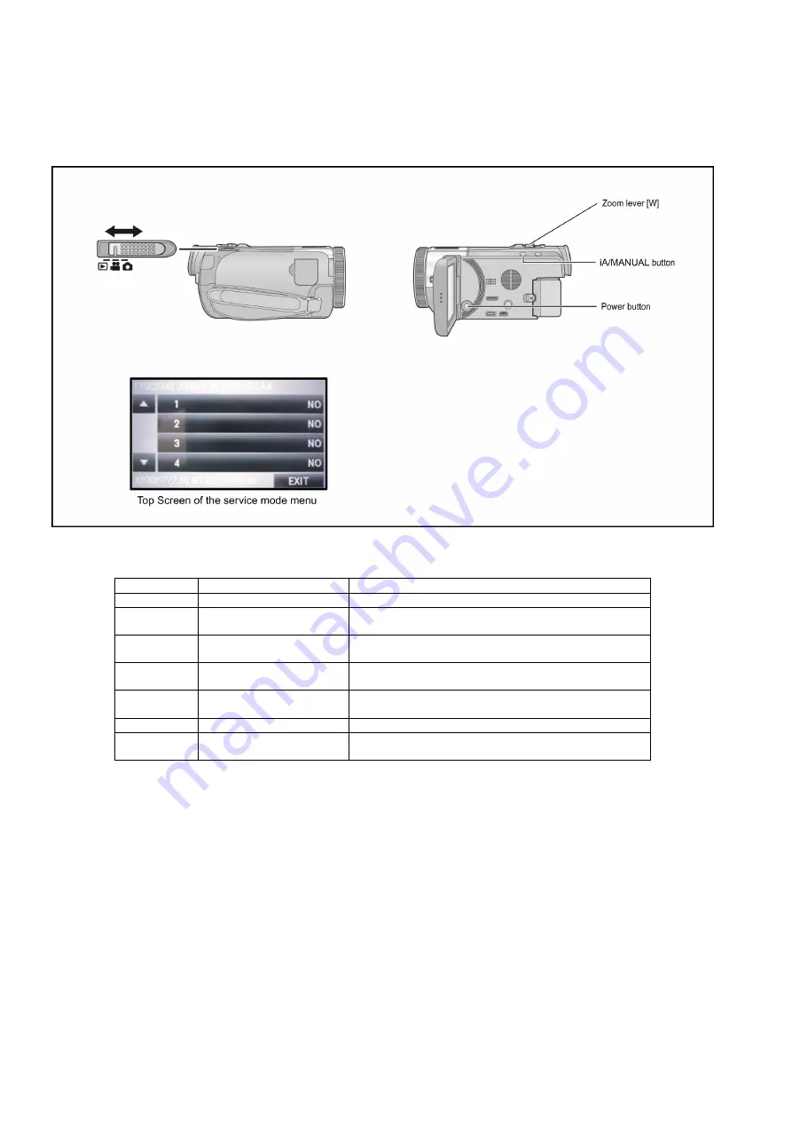
Indication method of the service menu
Set the mode switch "Motion Picture Recording" mode.
2. While the power is turned OFF, keep pressing the "POWER" button, "Zoom lever" to W side and "iA/Manual" button for more
than 3 seconds until the top screen of the Service Mode Menu being displayed.
Service mode menu
NOTE:
Do not using service mode except above table of Service mode menu.
3. End method of the top screen of the service mode menu
Touch the [ EXIT ] of LCD to end the service mode, and then POWER OFF.
Screen display
Contents
Function
1
Factory settings
Function to throw a product up in a factory shipment state
3
Built-in memory self check
exection (HC-X900M only)
Function to check self as for the state of Built-in memory
4
Lock search history indication Display the camera system error cord for three histories saved
in EEPROM
5
Power ON self check result dis-
play
Power ON self check (function to diagnose correct function of
the device and interface between devices) result display
9
Forced full flash emission
Forced full flash emission for discharging the capacitor on
FLASH P.C.B. and set to prohibit charge
10
Erasing the lock histories
Erasing the error histories (working time is not erased)
12
Camera data indications while
the video playback
Display the camera informations (Shutter speed, Iris value,
White balance and focal length) while playing recorded video
Summary of Contents for HC-X900MP
Page 10: ...10 3 5 Formatting ...
Page 11: ...11 4 Specifications ...
Page 12: ...12 ...
Page 13: ...13 ...
Page 14: ...14 ...
Page 15: ...15 5 Location of Controls and Components ...
Page 16: ...16 ...
Page 17: ...17 ...
Page 30: ...30 8 3 5 Removal of the Top OP Unit Fig D6 Fig D7 ...
Page 33: ...33 Fig D13 8 3 11 Removal of the Flash P C B Fig D14 ...
Page 37: ...37 8 3 18 Removal of the Barrier Case Unit Fig D25 Fig D26 ...
Page 39: ...39 Fig D30 Fig D31 Fig D32 ...
Page 40: ...40 8 3 21 Removal of the EVF Lens Holder Unit Fig D33 Fig D34 ...
Page 44: ...44 8 3 29 Removal of the MOS Unit Fig D44 8 3 30 Removal of the Stepping Motor Fig D45 ...


